Well, couple of weeks listening behind. It seems that my heatsink is way too big for this build and you have to really crank it up to get even a little heat. But it seems to make a difference, sounds much better after a while.
I have reserved my biggest sinks for Class-A anyways, so this will move into smaller case at some point (extra 4U laying around, without sinks), and thinking of smaller caps with cap multiplier. Can't do it just yet though.
Something is not right about your amp. Mine has big heat sinks and they feel as hot as class A at idle and cool down abit when you crank the volume. All the reviews I read about the original amp reported that the amp operates in this fashion and mine mimicks this behavior exactly.
I have the cards with 2 pairs of endings, those with protection, dual mono, one of the boards, at power up, the finals heat a lot, x which I tried with lower power, + 15volt-15, the finals heat a lot, almost to firing, on the capacitors I find + 8volt-8volt, a fall of 7 volts x branch, I shoot the protection, but the finals continue to heat, the other card is ok, with the same power supply, what can it be?
Thanks Danny.
The static polarisation network of the four power transistors is essentially identical to that of the two versions.
One 27 Ohm resistor on the Base (parallel to one diode) of each final BJT, with the addition of a 0.5 Ohm/5 Watt ceramic resistor on each of the individual Emitters.
Hi
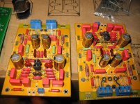
I am almost finished to populate my PC boards.
I have a couple of question
The emitter resistor value 0.22R acceptable or too low. The reason I ask people tend to use higher values like 0.5R or 0.66R. I am confused because Danny advised using a lower value like 0.1 or 0.22. I already prepared the 0.22R to stuff it but I thought I will ask.
I know to simulate a circuit and used in real life can be differences but Danny made always exceptional sim work on other amps like the Alpha.
Please, someone, let me know what value should I use, I have at hand 0.22R and 0.47R. I need to be sure, that Output PC board was stuffed several times already for Krell and Aleph 4 also. If I stuff it again with the wrong value and has to be removed I can throw those boards into the garbage.
 😱
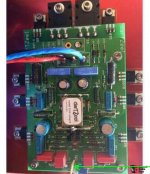
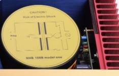
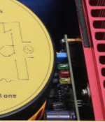
😱Second question where should I connect the DC wire?
Please take a look at the first picture, green arrow.
By the way, for stabilizing the amp I will use the super caps like the original.
Thank you
Attachments
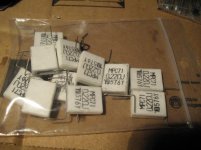
Speaking of the DarthZeel NHB-108 clone board, the 0.22 OHM resistors, as Danny suggests, are perfect and after initially installing the 0.5 OHM resistors I removed and replaced them.
The DC point highlighted in the first picture, I did not use it or even connect it, because it is essentially aimed at adjusting the Offset through the blue trimmer and is used in case you use the Servo DC card, alternative to the use of the Supercap that you will use.
And you're doing very well!
Congratulations on your initiative and good work.
And you're doing very well!
Congratulations on your initiative and good work.
Hi
Thank you for the answer, that helps a lot to know the amplifier works well in real life with the 0.22 emitter resistors
Now I can go on and finish the output boards.
I have to mount the supercapacitor to the bottom I do not have enough room at the top.
Someone at the Hungarian DIY forum re-engineered the (big) Dartzeel NHB-458 with 4 pair output transistors, he also uses low-value (0.22R) type emitter resistors (based on his simulation) and uses a high voltage rail power supply. More than180W/8R.
He built several great amplifiers with tubes and solid states also.
He wrote about the re-engineered Dartzeel-I ended up surprisingly with a great sounding amplifier, This amplifier is a keeper.🙂
Thank you one more time for your help, I was confused about those resistors.🙂
Hello everybody,
what do you think about modding the output stage to not allow transistors to switch off during opposite polarity semicycle? The schema is simple: remove the resistor paralleled with the diode and put a new resistor from base to collector. We have to substitute the 1N4004 by finding out which diode (must be fast, maybe a Schottky) with a suitable forwarding voltage will fit the needed idle polarization of the output stage, avoiding crossover distortion. The new resistor value should be easy to fix: 1/2Vb/desired I x hfe. The desired I is not the I idle but a current as low as possible to not allow transistor to switch off. Diodes and resistors must be as many as transistors. Just an idea to think on.
what do you think about modding the output stage to not allow transistors to switch off during opposite polarity semicycle? The schema is simple: remove the resistor paralleled with the diode and put a new resistor from base to collector. We have to substitute the 1N4004 by finding out which diode (must be fast, maybe a Schottky) with a suitable forwarding voltage will fit the needed idle polarization of the output stage, avoiding crossover distortion. The new resistor value should be easy to fix: 1/2Vb/desired I x hfe. The desired I is not the I idle but a current as low as possible to not allow transistor to switch off. Diodes and resistors must be as many as transistors. Just an idea to think on.
What are these extra boards for?
I wish buying stuff from Aliexpress was easier. They always have multiple version, unclear description of what you actually get and what you DON'T get.
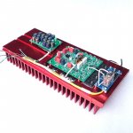
If you look att the more expensive NHB-108 listings they have a PCB next to the trafo, which basically looks like a power filter with caps. Some version have three leds (R,G,B). What are these things? Where do you get them?
Mounted on the heatsink, except the amp, you see one of these cap arrays boards and then a relay board next to the MJE13033's. That's some kind of protective circuit if you have no speakers connected I get that, but where do I buy one?
PS. Planning on doing a 3 channel amp based on NHB-108 boards (so basically a 1,5x NHB-108) for my home cinema.
I wish buying stuff from Aliexpress was easier. They always have multiple version, unclear description of what you actually get and what you DON'T get.
If you look att the more expensive NHB-108 listings they have a PCB next to the trafo, which basically looks like a power filter with caps. Some version have three leds (R,G,B). What are these things? Where do you get them?
Mounted on the heatsink, except the amp, you see one of these cap arrays boards and then a relay board next to the MJE13033's. That's some kind of protective circuit if you have no speakers connected I get that, but where do I buy one?
PS. Planning on doing a 3 channel amp based on NHB-108 boards (so basically a 1,5x NHB-108) for my home cinema.
Attachments
it seems they have an overpriced premium version
The latest Black Widow Power Amp Amplifier Multi Mode Bridging Balance 8 ohm 350W 2018 Version Dartzeel NHB358 Study Version -in Amplifier from Consumer Electronics on Aliexpress.com | Alibaba Group
Three versions in all a standard an update and a luxury.
The luxury has the same capacitor configuration as the original .
Hi guys!
Somebody bought this kit of dartzeel?
Прямо к карлик dartzeel NHB 108 пост усилитель купить на AliExpress
The seller claims that transistors are picked up with an accuracy of 1%.
It is the truth or deception?
Somebody bought this kit of dartzeel?
Прямо к карлик dartzeel NHB 108 пост усилитель купить на AliExpress
The seller claims that transistors are picked up with an accuracy of 1%.
It is the truth or deception?
Hi all! Let me start by saying that this is a fantastic amplifier that made me put my Bryston 4BST to sleep in it's factory box. My clone of NHB108 was made by my father but I'm not so sure he did the dc offset setting correctly, I am hearing a low level noise coming from my speakers when it should be quiet ( to be exact, sometimes it's absolutely quiet, but not yesterday for example ). There are speaker protection modules for the speakers and they do not activate, so this tells me that it's not a dangerous dc voltage to the speakers but all of this makes me think that there may be something wrong with the adjustments and I would appreciate it if someone could guide me on the way to do it correctly.
Thanks in advance!
Thanks in advance!
Whatever noise you hear is unrelated to the presence or absence of dc. It may not even be related to the amp, but to the source, grounding issues, mains noise, etc.
As for the dc offset, if you have to ask on forums how to measure it, you should probably leave it to your father to adjust.
As for the dc offset, if you have to ask on forums how to measure it, you should probably leave it to your father to adjust.
Whatever noise you hear is unrelated to the presence or absence of dc. It may not even be related to the amp, but to the source, grounding issues, mains noise, etc.
As for the dc offset, if you have to ask on forums how to measure it, you should probably leave it to your father to adjust.
Let me explain. I have been searching for the procedure to set the dc offset in general, and found that the inputs have to be shorted and there should be only multimeter connected to the output in order to measure the dc offset. On the other hand, I've read that NHB108 should not be operated without speakers connected or else the output will be fried ( this is due to the absence of the zobel network if I'm correct? ). My father has made the measurements with speakers connected and without shorted inputs. Since I can't find any guideline for this specific amplifier and since lots of people have built it in this forum, I came for advice.
For a start, I need to know which is the safest ( for the amplifier, I will take safety measures for myself, gloves, glasses ) way to measure the dc offset, and if needed, which is the procedure to set it correctly.
never connect it to the speakers, but test it with the load (which may not be the speakers)
verify the offset with multimeter, cold and then hot.
use a multiturn trimmer
verify it within a few hours
The 22 mf capacitor to ground serves to control the output offset
avoid the servo circuit
in my opinion
I made a clone but with 4 pairs of finals
verify the offset with multimeter, cold and then hot.
use a multiturn trimmer
verify it within a few hours
The 22 mf capacitor to ground serves to control the output offset
avoid the servo circuit
in my opinion
I made a clone but with 4 pairs of finals
never connect it to the speakers, but test it with the load (which may not be the speakers)
A resistor as a load, for example those 8R 100W that being sold in ebay?
I've read about the benefits of placing the supercapacitor, I am considering the purchase. Of course, I will need some help on how to place them on board since i see in pictures that, but it's not something to examine at this moment.
- Home
- Amplifiers
- Solid State
- Dartzeel amp schematic - build this?