Remove one pair of power transistors?
Can one simply remove one pair of transistors on a two pair version? (And maybe change the value of power resistors?)
I planned to buy a two pair version, and simply remove one pair if the heat sinks become too hot or if there is a bias problem. Is that not possible?
I also bought the one pair version. No problem with that. The two pair version have a bias problem. It is all to low. Yesterday I saw the two pair version on their site.
Can one simply remove one pair of transistors on a two pair version? (And maybe change the value of power resistors?)
I planned to buy a two pair version, and simply remove one pair if the heat sinks become too hot or if there is a bias problem. Is that not possible?
Amp Input PCB configuration and diagram
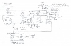
Hi. Did someone ever wonder what was the inputs selection/configuration of the original amp? Is it possible that some kind of buffer, possibly a simple two JFET buffer was on the rear input pcb, and was before the amp pcb? Here is what I think I found from reading the user manual and some post on the net:
-The manual said: 'when connecting to the XLR or the RCA input, select the 50ohms input to prevent any pop and/or noise'. Probably means that the RCA/XLR are switched by a relay, and that the 50ohms is straigt to the amp.
-From picture the 50ohms input seems to be terminated in a 50R resistor, and then goes by a short lenght of coax directly to the 'DC' input pad on the amp pcb.
-The 'B' version has the 'DC Comp' circuit, that can be activated or not using a jumper.
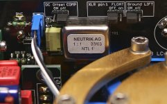
-The XLR input is done using a Neutrik NTL1 1:1 balanced line transformer. Possibly the RCA is connected just after this transfo secondary.
-The Audio out of the rear pcb goes directly to the amp audio input using a twisted pairs of wires.
-The rear PCB seems to have a servo circuit for the 'DC Comp', supplied directly from the amp supply through two 4k7/3w and zener power supply, probably +-12 or 15V for the op-amp. The PCB pictures seems to indicate a +15V TP, near the relay... This +-V supplies are connected by a small 3 wires conenctor on the bottom.
-An other 3 wires connectors on the top seems to go to the proctection circuit. Possibly the two small to92 are part of the protection, and are not a JFET buffer. The Protection circuit needs to monitor the speaker+ binding post for the different voltage alarm thresholds. So my guest is that this connector is for the protection...
A few questions:
-how is the Servo DC correction voltage is going to the main amp circuit? The 50ohms input seems to go directly to the DC pad, but isn't this pad also the output of the DC adjustment pot? In this case is the clone pcb correct?
-If not is the Servo voltage added to the Audio In signal, but this is cap coupled at the amp input?
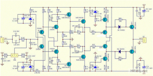
Check my pictures and possible amp input circuit diagram. I need to change it to reflect the direct 50ohms input by coax...
Comments are welcome...
SB
Hi. Did someone ever wonder what was the inputs selection/configuration of the original amp? Is it possible that some kind of buffer, possibly a simple two JFET buffer was on the rear input pcb, and was before the amp pcb? Here is what I think I found from reading the user manual and some post on the net:
-The manual said: 'when connecting to the XLR or the RCA input, select the 50ohms input to prevent any pop and/or noise'. Probably means that the RCA/XLR are switched by a relay, and that the 50ohms is straigt to the amp.
-From picture the 50ohms input seems to be terminated in a 50R resistor, and then goes by a short lenght of coax directly to the 'DC' input pad on the amp pcb.
-The 'B' version has the 'DC Comp' circuit, that can be activated or not using a jumper.
-The XLR input is done using a Neutrik NTL1 1:1 balanced line transformer. Possibly the RCA is connected just after this transfo secondary.
-The Audio out of the rear pcb goes directly to the amp audio input using a twisted pairs of wires.
-The rear PCB seems to have a servo circuit for the 'DC Comp', supplied directly from the amp supply through two 4k7/3w and zener power supply, probably +-12 or 15V for the op-amp. The PCB pictures seems to indicate a +15V TP, near the relay... This +-V supplies are connected by a small 3 wires conenctor on the bottom.
-An other 3 wires connectors on the top seems to go to the proctection circuit. Possibly the two small to92 are part of the protection, and are not a JFET buffer. The Protection circuit needs to monitor the speaker+ binding post for the different voltage alarm thresholds. So my guest is that this connector is for the protection...
A few questions:
-how is the Servo DC correction voltage is going to the main amp circuit? The 50ohms input seems to go directly to the DC pad, but isn't this pad also the output of the DC adjustment pot? In this case is the clone pcb correct?
-If not is the Servo voltage added to the Audio In signal, but this is cap coupled at the amp input?
Check my pictures and possible amp input circuit diagram. I need to change it to reflect the direct 50ohms input by coax...
Comments are welcome...
SB
Attachments

Can one simply remove one pair of transistors on a two pair version? (And maybe change the value of power resistors?)
I planned to buy a two pair version, and simply remove one pair if the heat sinks become too hot or if there is a bias problem. Is that not possible?
I think it is possible. But wait and se what others answers.
Hi Algar
I fear some of your speculation is unjustified
- no, there is no buffer as there is simply no need for a buffer
- no, there is no servo in any of the 108 modifications, instead there is a jumper selectable negative feedback decoupling cap
- yes, the rca connections follow the transformer. The quality of sound through that miserable transformer is of course atrocious, no one in their right mind would listen through it, it is just a simple answer to the market pressure of having a balanced input
Can one simply remove one pair of transistors on a two pair version? (And maybe change the value of power resistors?)
I planned to buy a two pair version, and simply remove one pair if the heat sinks become too hot or if there is a bias problem. Is that not possible?
I think it is possible. But wait and se what others answers.
No need to panic and allarm firefighters. 😉
Even at very high rail voltage, slightly over +-63°C output transistors of NHB-108 never were really too hot.
In case you have problems you still can use a silent PC fan to cool it down. But as I understand Erlend had quite the opposite problem: his transistors weren't biassed properly and have remained cold.
In my view these versions with multiple pairs seem to be more nuisance than solution to the problem, if any.
Friends, have a pleasant week end.🙂
PS: I'm glad to see that conversation among experts develops here: Algar & Analog. I'm looking forward to learn quite a bit from them.
Last edited:
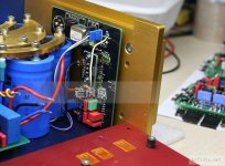
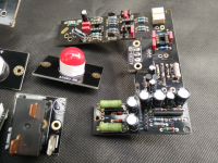
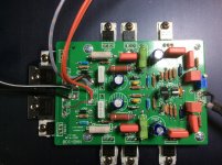
Hi Analog_sa, thanks for the comments. I never tried the Neutrick transformer, glad to hear that it is not worth trying. Doesn't mean that all balanced input transformers are equal. I used Lundhall in the past and they are quite good. So if a balanced input is desired probably the INA134 BAL/SE Converter would be a cheaper and better sounding solution? I saw some Chinese clone maker that form the picture seems to have implemented an opamp based converter. The bottom part of the pcb has also the uPC1327 protection circuit, see picture.
Also glad to hear that these two transistors are not for a buffer, it was just a theory...
What do you think of the opamp circuit on the bottom of the rear pcb, looks like a servo circuit to me? Or maybe it is a DC output detection circuit for the protection?
So you think the the 'DC Comp On/Off' jumper is to connect the super cap or not into the amp circuit?
The top 3 pins connector seems to go to the Current transformer that sense the output current, possibly to transport the +15V for the sensor, Colors are the same, look ate the connector on the back of the transfo pcb... The one on the front goes to the protection pcb...
Thanks
SB
Attachments
Last edited:
Offset unstable need help
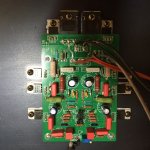
I have finish assemble my two Chinese Dartzeel kit version one.
I bought a lot of 2N5401/2N5551 and pair it.
I controled each componant supplied all value were good or close to the value for resistor and caps ESR correct.
I supply with standard non stabilised dc power +-55Vdc impossible to fix the offset so I use stabilised cc power +-39v dc and also impossible to fix the offset always moving could be +600mv and later -500mv two hours later always moving.
no input or shortcut input the same, no output or 8 ohm resistor the same,only one channel the same.
Ar the output of the trimmer I could measure dc moving for exemple -23.6mv to -27.3mv each side of the trimmer +0.5v and the other -1v
Rail current is 410mA
Whan close to 100mv offset during short time I could listen music and I think it will be verygood once offset fixed.
Please what to do to stop the offset moving?
Many thanks
Attachments
Pick up the input four in 1 percent.2N5401/2N5551
Hi Paroxod4, sorry I cannot understand what you mean four in 1 percent (french)😕 2N5551/2N5401 are actually paired (same hfe) and sticked together.
I have finish assemble my two Chinese Dartzeel kit version one.
I bought a lot of 2N5401/2N5551 and pair it.
I controled each componant supplied all value were good or close to the value for resistor and caps ESR correct.
I supply with standard non stabilised dc power +-55Vdc impossible to fix the offset so I use stabilised cc power +-39v dc and also impossible to fix the offset always moving could be +600mv and later -500mv two hours later always moving.
Many thanks
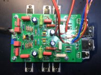
Your problem you do not have either the supercapacitor either the offset stabilized. Like that you can not use the amplifier!
It will remain unstable!

You need to do something to stabilize the offset.
See the picture for the capacitor or the extra stabilizer circuit, you need one of those. 🙂🙂
Greetings
Attachments

Thank you Gaborbela, I think read on this forum that the the supercap or extra stabilizer were not good for the sound result is there no other way to stabilize the offset?
I will check to place a 22000µf capacitor between r9-r10 and ground.
I will check to place a 22000µf capacitor between r9-r10 and ground.
Last edited:
Please what to do to stop the offset moving?
My offset requires adjustment every few months. Input transistors are very loosely selected; in one amp they are in thermal contact, in another they are not. No difference. Otoh, both amps are not boxed, so that may be a factor.
I believe i have written about this before. The input circuit is sensitive to offset because of the large resistor values in the offset correction. These resistors also determine the input impedance and the minimum size of the coupling caps but can easily be reduced 2-3 fold with no ill effects.
I used Lundhall in the past and they are quite good.
Hi Sylvain
Not a big fan of any of the small core transformers, have a bunch of Lundahls and would rather use opamps instead, at least they won't screw the bass up so badly.
As much as i like and prefer balanced connections i feel these are beneficial only when the circuit topology is "naturally" balanced, per example when an input stage is built around a differential amp. If additional circuitry is required for obtaining either a balanced input or a balanced output, then the sonic benefits are often cancelled entirely by the additional circuitry. Ime this is true of 90% of factory made balanced equipment which sounds much better when used with SE connections.
There is no need to look so hard at the 108 pictures, the absence of a servo is a widely known fact, it is not a guess.
That's perfect but the amp is absolutely not. But your DC problems must be the worst I ever heard. Are your other transistors mounted correct to enclosure. Do you have a picture?Hi Paroxod4, sorry I cannot understand what you mean four in 1 percent (french)😕 2N5551/2N5401 are actually paired (same hfe) and sticked together.
My offset requires adjustment every few months. Input transistors are very loosely selected; in one amp they are in thermal contact, in another they are not. No difference. Otoh, both amps are not boxed, so that may be a factor.
I believe i have written about this before. The input circuit is sensitive to offset because of the large resistor values in the offset correction. These resistors also determine the input impedance and the minimum size of the coupling caps but can easily be reduced 2-3 fold with no ill effects.
do you think I could put 510k in parallel on each 510k without problem and with succès?
Hi Erlend the both the same comportment 😕That's perfect but the amp is absolutely not. But your DC problems must be the worst I ever heard. Are your other transistors mounted correct to enclosure. Do you have a picture?
I will install a 22000µf cap but before make a trial I need to dissolder the common side of the 360ohm resistor from the top.
Attachments
do you think I could put 510k in parallel on each 510k without problem and with succès?
I would make it much lower in order to see if there is any improvement. 100k or even 50k.
@dugain
Perhaps you should just let the amplifier run for a while to "burn-in". It takes long time to bring it to stable higher temperature - several hours. Then let it run, overnight. But be carefull - neighbours might call police if you let it play overnight at full volume. 😉
Don't rush to solve the problem that might doesn't really exist. Patience. I have followed analog_sa advice and it works for me.
For time being I have two pairs: the one with capacitor between resistors R9 and R10 and ground and another without that capacitor. There is no such capacitor on the "original" schematics. And it seems to me that it doesn't have some audible effect.
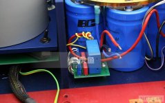
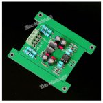
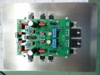
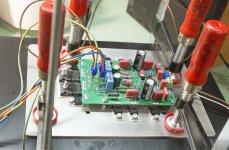
Here I have attached two recent photos: I have tested thermal behaviour after inserting alumina thermal pads. They transfer heat much better than mica even though alumina pads are thicker but they have much higher heat transfer coefficient: about 30 times that of mica. Astonishingly, alumina has higher heat transfer coefficient than stainless steel!
I have also installed the board on aluminum plate as Hattori has suggested and then fixed it to the heat sink with vices just for test purposes. Afterwards I will use four M5 screws to fix the assembly on the heat sink. (Observe these holes near the edges of the board). Thermically this setup seems to work wonderfully and allows easier dissassembly if needed. Also M5 threads are mechanically much more durable than M3.
Perhaps you should just let the amplifier run for a while to "burn-in". It takes long time to bring it to stable higher temperature - several hours. Then let it run, overnight. But be carefull - neighbours might call police if you let it play overnight at full volume. 😉
Don't rush to solve the problem that might doesn't really exist. Patience. I have followed analog_sa advice and it works for me.
For time being I have two pairs: the one with capacitor between resistors R9 and R10 and ground and another without that capacitor. There is no such capacitor on the "original" schematics. And it seems to me that it doesn't have some audible effect.
Here I have attached two recent photos: I have tested thermal behaviour after inserting alumina thermal pads. They transfer heat much better than mica even though alumina pads are thicker but they have much higher heat transfer coefficient: about 30 times that of mica. Astonishingly, alumina has higher heat transfer coefficient than stainless steel!
I have also installed the board on aluminum plate as Hattori has suggested and then fixed it to the heat sink with vices just for test purposes. Afterwards I will use four M5 screws to fix the assembly on the heat sink. (Observe these holes near the edges of the board). Thermically this setup seems to work wonderfully and allows easier dissassembly if needed. Also M5 threads are mechanically much more durable than M3.
Attachments
Last edited:
- Home
- Amplifiers
- Solid State
- Dartzeel amp schematic - build this?