There's now also a DC servo
If using the DC servo you can remove the input caps and the DC trimmer,
the amp becomes then DC coupled.
The SNCP cap is also not needed anymore, that's the single cap in the middle.
Yes have came across the link which you have shared, couldn't understand how to use 😉
Both exactly same in case of performance or the design?
The PCBs are basically the same, the douk audio boards use a floating avx Bestcap (its mounted suspended above the pcb) and the V0.2 boards did away with the floating avx capacitor and has a electrolytic capacitor mounted on the pcb board. Components and values looks the same to me.
Yes have came across the link which you have shared, couldn't understand how to use 😉
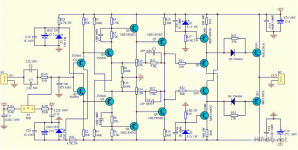
Look at the schematic halfway at the following page
- remove the DC trimmer P1, input caps C6 and C7 can also be bypassed
- the DC servo has two outputs, connect one output between resistor R9 and transistor Q3, the other output between R10 and Q4
That's it, you now have a DC coupled amplifier with zero DC output 🙂
Question
How that will effect the final sound if that not cloned after the original.
One should ask about before you purchase it or at least do A-B test with and with out.
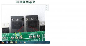
Is these ON Semi power device original? I do have at least 45 pair direct from On semi (two separate purchase) and mine does not have those teeth like support on the pin out.
Attachments
The PCBs are basically the same, the douk audio boards use a floating avx Bestcap (its mounted suspended above the pcb) and the V0.2 boards did away with the floating avx capacitor and has a electrolytic capacitor mounted on the pcb board. Components and values looks the same to me.
Observed any difference in quality of sound or quality of parts used between 2 sources?
I've simulated the DC servo in LTspice to see how it reacts, the DC servo has a very low lowpass filter.Question
How that will effect the final sound if that not cloned after the original.
One should ask about before you purchase it or at least do A-B test with and with out.
In Ltspice it looked very good so I went ahead,
by using the DC servo I could get rid of the input blocking/coupling caps and the DC trimmer.
So it was choosing between DC servo or input caps.
Now I'm rebuilding the amp with more output pairs (2 or 3 pairs) and also separate transformers + PS for each channel, with only one transformer I have hum.
Is these ON Semi power device original? I do have at least 45 pair direct from On semi (two separate purchase) and mine does not have those teeth like support on the pin out.
Yes, it seems to be a newer original, OnSemi changed it according to this post.
I've simulated the DC servo in LTspice to see how it reacts, the DC servo has a very low lowpass filter.
In Ltspice it looked very good so I went ahead,
by using the DC servo I could get rid of the input blocking/coupling caps and the DC trimmer.
So it was choosing between DC servo or input caps.
Now I'm rebuilding the amp with more output pairs (2 or 3 pairs) and also separate transformers + PS for each channel, with only one transformer I have hum.
Yes, it seems to be a newer original, OnSemi changed it according to this post.
Thank you for your answer and for the sim.
You know between sim and real life listening can be differences, what I want to say if I were you I would do a honest A/B listening test with a friend or two. Getting rid of the input caps sometimes time is good but not always, sometimes it used for other purpose not just DC blocking. Very often people use 100uF bipolars.. 🙂 If you look at the attach. pic. the guy do not remove the input caps when he ad the DC servo. Very likely he follow the original amp with that to, but I'm not sure.😕 Just make sure on the end you can compare the orig clone with the one you you plan to build. You may improve the overall performance
 but it may not have the sound character as the Dartzeel, you know what I mean.
 With the 3 pairs power device which PC board you plan to use, or you design your own or point to point in a bread board
Reason I'm asking because I plan to buy a pair of the gold color PC board. Later at these year I may build and test these amp. I have all the semis at home some big power transformer and PS caps.
Please keep inform us with your progress
Thanks
Attachments
Yep, a simulation is not the complete story but a nice guideline 🙂
Without a DC servo the DC bias is done by injecting DC at the signal input, before the first transistors.
So the input caps are needed to not offset the DC bias when there is DC on the input signal from the preamp or source.
Most commercial products have input/output caps, just to make them more foolproof.
But as DIYer I know very good what the previous component feeds to my amps, I hope 😉
I use the following PCBs for 3 pairs or 2 pairs
but with the operating points of the transistors optimized for 4 ohm speakers by changing some resistor values.
The multiple pairs output have additional source resistors for better stability and matching of the output pairs.
I've also added speaker protection, added a 20watt 6ohm resistor to the open circuit for when the relays are not connected to the speakers, so the output stage has always a load.
Definitely use two transformers so you can build completely separated channels, with one transformer I had hum.
Regards,
Danny
Thanks one more time for your answer
Did you buy the kit or just the PC boards?
I only interested on PC boards, try to avoid to buy any semiconductor including kits from Ebay or similar sources due to flood of counterfeit parts.
Did you buy the kit or just the PC boards?
I only interested on PC boards, try to avoid to buy any semiconductor including kits from Ebay or similar sources due to flood of counterfeit parts.
I've simulated the DC servo in LTspice to see how it reacts, the DC servo has a very low lowpass filter.
Is there a circuit for the servo?
Just the PCBs, only the DC servo was complete.
Hi
The reference you gave me ( with the 2 & 3 pair power device) they only sell the whole kit.
I'm strictly interested to get the bare amplifier PC boards, no parts at all.
If I understood well these layout follow the original layout what I think is very important.
Only I found bare PC board with one pair power transistors.
I'm not talking about the DC servo!
Are you sure you get only the amplifier PC boards and not the whole kit, or they just try to trick me to buy the whole dam think.😕
I do not wish to invest any amount of fund into fake or counter faith semiconductors meanwhile I have the original at hand. 😉
To me not urgent, but if I see the mentioned PC board I will buy it ASAP.
I have never seen the pcbs forsale anywhere. Douk audio is the only place that sells the un assembled kits. You should contact them and ask if they will sell u the pcbs alone
I'm 100% sure I bought just the PCBs 🙂Hi
Are you sure you get only the amplifier PC boards and not the whole kit, or they just try to trick me to buy the whole dam think.😕
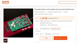
I've checked the links and for the dual pair it's still possible to buy only the PCB's, but you have to select the "color" option.
Here's a screenshot of the page translated to English in Google Chrome.
If you contact the seller you probably can also buy the triple pairs, use a good agent like taobaoring.com
Attachments
I'm 100% sure I bought just the PCBs 🙂
I've checked the links and for the dual pair it's still possible to buy only the PCB's, but you have to select the "color" option.
Here's a screenshot of the page translated to English in Google Chrome.
If you contact the seller you probably can also buy the triple pairs, use a good agent like taobaoring.com
Thank you
Yes you right about that, the 2 pairs PC boards available the 3 pairs not. Only option the full kit.
To contact with them for any reason one must register, I do not see Pay Pal payment option that it worries me a bit.
With Pay Pal the transaction is safe, to give out my Credit C information😱
I will register let see..
Before I was looking wrong place at Ali Express
Hi guys: I ordered my version, and have a coupe of concerns... where should i start... 🙂
1) Using thermal pads for the first time... Is it a good idea? The issue I have is that the driver mje15034/35's (q9/10/90/100) get very hot, but I dont want to further tighten the bolts to the heatsink since the pads compress, and might just puncture... having said that, the heatink stablizes at 54c running a 4 ohm load at 1/3rd power intermittent music... the drivers are still alive, so perhaps the thermal pads are ok?
2) The predrivers (Q7 and Q8) were pre-mounted on their own little TO-220 heatsinks and run awfully hot. I measure between 68-74c on those tiny sinks... how can I reduce the current flowing through them? Should I increase R15/16 to 68ohms from 47? (see generic schematic, my values a bit different) or is 74c ok.
3) The OP devices seem ok and cool to touch, but the drivers and their current source (q9/10 and q90/100) are mounted on the main heatsink and are very hot to touch even on the plastic front side. Again, its been running for 30 minutes and nothing smoked yet... Is it ok for the heatsink to be running at 55c or so?
Sound: At the moment I only have a pair of baby Advents to listen with. First impressions... The sound is overly warm, lacks details that I get from my old Kenwood KA-1100sd integrated. The bass is also loose compared to the Kenwood. But I like the softness of the vocals, seem quite real. With burn in sounds better...
PS: There are no output emitter resistors on this guy... how do I measure the OP bias?
Thanks
Attachments
Last edited:
PS: There are no output emitter resistors on this guy... how do I measure the OP bias?
Thanks
Just use the DMM connect between the PS positive ad the PC boards positive. Set your DMM to 200mA (for these amp) before you ad any power and what ever you read after warm up that is the total bias.
It es easy I always do that way and very accurate to set up any amp bias or check if it has any drift etc.
Tks Gaborbela, sounds logical, but how should I trim it? I'd rather it do 5 watts class A instead of 20 given that this version I am building is in a smallish enclosure. I'd rather not have to install fans
Hi K-amps,
Here some answers:
1) Those thermal pads are not good with those TO-220 transistors, I had them punctured by the sharp edges.
Much better are Alumina (aluminium oxide)
2) The layout of the PCB is not that good, the predrivers are not on the main heatsink. The original PCB layout is better.
Try to install larger heatsinks
With 36ohm the predrivers get 55ma/2.9w, with 47ohm its 42ma/2.2w, but 47ohm will raise distortion.
I would also change R9/R10 from 360 to 470 ohm, that will lower distortion.
Another option is the FB R11/R12 resistor, changing it to 6.2-6.8k will also lower distortion.
So predrivers 47ohm + R9/R10 470 ohm + R11/R12 6.8k will still give lower distortion
For the sound it is not lacking details, it's comparable with my F5.
Agree on the loose bass, bass is more than F5 but not enough controlled.
Use a very good MKP capacitor for C6/C7.
The output stage is biassed at around 180ma/10w per transistor
Regards,
Danny
Last edited:
- Home
- Amplifiers
- Solid State
- Dartzeel amp schematic - build this?