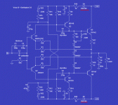
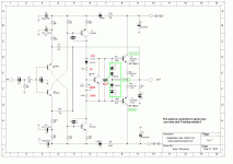
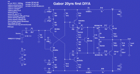
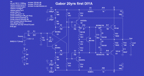
Ok , understood. I'll try againI just made copies of the transistor symbols and renamed them appropriately.
Thanks a lot
J.
Hi
I don't think these two diode is correct.
You suppose to use some 1N4007 or something stronger and high speed
Please apply some VBE for the bias monitoring
How I wrote I used something similar circuit (I believe LC borrowed the idea from that) and I achieved incredible great sound (best sounding amplifier ever built) but I do have issue with thermal drifting and I burn my amp and some midwoofers with that.
Now I work on it to stabilize the thermal drifting.
The reason I van to follow your thread. ACA also posted some stuff to the thread I opened.
I do not have access to run some simulation so it is hard to check the circuit.😕
Greetings gabor
Attachments
A Darlington output stage has 4 Vbe drops. These all change with temperature. You need to replicate that with your thermal sense. Diodes aren't great as they can't be well attached to the heatsink. Use a transistor Vbe multiplier and bolt it to the heatsink that the output devices are on.
Why all this fuss over darlingtons ? A small cheap EF2 can be made for
7-8$ (with a real mje340 Vbe).
1- mje340 / 2 - to-126 /to-220 drivers and a pair njw/ or sanken mt-100's.
A real EF2 works real well with the VSSA. I see no advantage in the
darlington , quite the opposite.
OS
7-8$ (with a real mje340 Vbe).
1- mje340 / 2 - to-126 /to-220 drivers and a pair njw/ or sanken mt-100's.
A real EF2 works real well with the VSSA. I see no advantage in the
darlington , quite the opposite.
OS
I do agree there are real advantages to going with a discrete EF2 or EF3 for sure, but for really cheap and low physical device count devices like the TIP142 / TIP147 (and of course nicer audio specific devices like Sanken) can actually sound surprisingly good. I've built a few smaller amps using darlingtons and they work fine if you don't get to thinking that they are capable of too much. I wouldn't exactly run about extolling the virtues if darlingtons, however, if you have 'em already or can get them easily and cheaply compared to more desirable devices... Go for it.
If someone wants to take that little VSSA / PeeCeeBee concept and throw pretty much whatever output design at it it will almost certainly please when operated within its limits. We have seen Lateral MOSFETs, BJTs in EF2 / EF3, and Vertical MOSFETs used in both very simple and much more elaborate implementations, all to good effect.
If someone wants to take that little VSSA / PeeCeeBee concept and throw pretty much whatever output design at it it will almost certainly please when operated within its limits. We have seen Lateral MOSFETs, BJTs in EF2 / EF3, and Vertical MOSFETs used in both very simple and much more elaborate implementations, all to good effect.
I do agree there are real advantages to going with a discrete EF2 or EF3 for sure, but for really cheap and low physical device count devices like the TIP142 / TIP147 (and of course nicer audio specific devices like Sanken) can actually sound surprisingly good. I've built a few smaller amps using darlingtons and they work fine if you don't get to thinking that they are capable of too much. I wouldn't exactly run about extolling the virtues if darlingtons, however, if you have 'em already or can get them easily and cheaply compared to more desirable devices... Go for it.
If someone wants to take that little VSSA / PeeCeeBee concept and throw pretty much whatever output design at it it will almost certainly please when operated within its limits. We have seen Lateral MOSFETs, BJTs in EF2 / EF3, and Vertical MOSFETs used in both very simple and much more elaborate implementations, all to good effect.
I only commented as ON only specifies a common emitter freq. plot. (slow, BTW)
No Cob , no Ft. 142/147 are switches/relay drivers. most likely dog
ar$e slow. VSSA design would benefit from a known fast device
(as we all know). One of those Sanken darlington's with integrated
thermal diodes would be much better.
CFA's supposed SQ is it's speed . 142/147 might negate the design
goals.
OS
I did replaced in my circuit the darlington device (at that time I used BDW83C & 84C from Texas Inst.)
I used Motorola power device similar to MJL21193 & 94 some BD drivers but it sounded awful compare to the darlington.
May be I did something wrong way back 25 years a go. Reason I replaced the darlingtons because the Motorola more powerful easier to be matched.
Also at that time I did had the thermal draft issue (I thought the darlington to week)
I did not give up on my amp which is similar to these, I do have some Sanken darlingtons to.
The LatFet version has less punch in bass area, I don't know the vertical.
To me the darlington device has warmer sound like the regular BJT.
Maybe has higher distortion not sure.
Al do my circuit very similar still has some differences between the two.
These simple circuit very sensitive to each transistor and other parts. I mean it effect the sound a lot.
My Toshiba version (not tested yet)🙂
I encourage you not to give up on these amp, but please pay a lot of attention to be stable. The best would be use speakers protection.
Greetings gabor
Attachments
That's exactly the reason for me to build this circuit, and not any other more complex with 10+ or so active devices. Sound performance that I experienced with the first basic circuit, was enough to convince me. Sure much more is possible, but not with only six transistors / channel. I am aiming for 80 to 100W on 4 ohm loads, just for security, and then use the circuit exclusively with 8 ohm nominal loads.but for really cheap and low physical device count devices like the TIP142 / TIP147 (and of course nicer audio specific devices like Sanken) can actually sound surprisingly good. I've built a few smaller amps using darlingtons and they work fine if you don't get to thinking that they are capable of too much.
" most likely dogar$e slow" ahaha!! fantastic image, LOL!
Nevertheless my dog feeds with a lot of fiber and healthy food, because 150us rise time is quick enough evacuation time😛
JK, Gazza, Gabor, OS, thanks for a lot of useful stuff, tips and ideas. Give me a couple of two days to prepare an updated board with some of the suggested mods.
BTW, as VSSA is a trademark of Lazy Cat, what is an appropriate technical name-description for this type of not LTP IPS?
Last edited:
...
BTW, as VSSA is a trademark of Lazy Cat, what is an appropriate technical name-description for this type of not LTP IPS?
It is a sort of dual symmetric singleton. Cut the circuit in half and see how much it resembles the JLH singleton input. Kinda.
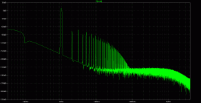
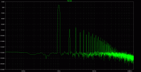
The slope is likely from the capacitor time constants, especially input coupling and feedback network. For simulation you can either make them impossibly large, like 100F, or replace them with voltage sources of the same magnitude as the DC value developed across them as found by the DC operating point analysis indicates. Also, when plotting the FFT change the number of points to something more like 8192 to give a more realistic 'floor'.
Also, the darlington models are just from ON Semiconductor IIRC, so they might not be the best models out there.
Also, the darlington models are just from ON Semiconductor IIRC, so they might not be the best models out there.
neverending learning journey
that's much better:
that's much better:
Attachments
Last edited:
Work in progress, now trying a discrete darlington config. Slow pace maybe, but not a chance of give up, no sir. Will report asap.
Hi
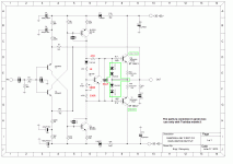
Can you run a sim for me on my circuit. Using TIP147 & TIP142 power darlingtons
I use these those MJE transistors for VAS because it gave me the best performance. I spent countless hours to much all the semis together to get great sound.
Please if you can run a simulation on these circuit
The green extra pieces if I use Toshiba mosfets only.
Thank you very much🙂 I have PC board layout if you interested
Attachments
Hi
Can you run a sim for me on my circuit. Using TIP147 & TIP142 power darlingtons
Hi Gabor, I can, as long the sistors are in the default LTSpice library, or in the Cordell library. Let me check. The TIPs models were gentle provided by Jason K.
BTW I have a strong feeling that this 'dual symmetric singleton' input stage is strongly dependant on the real life behaviour of real life components, so sims are to be looked with more caution than ever..
Hi
Bigun advised to increase up to 22 to 33uF electrolytic to resolve the thermal drift problem.
I did not tested with that high capacitor yet.
The 100nF for the mosfet version.
I never measure the voltage of that. The VBE just got modified based on Bigun advise.
Greetings
Bigun advised to increase up to 22 to 33uF electrolytic to resolve the thermal drift problem.
I did not tested with that high capacitor yet.
The 100nF for the mosfet version.
I never measure the voltage of that. The VBE just got modified based on Bigun advise.
Greetings
Last edited:
- Status
- Not open for further replies.
- Home
- Amplifiers
- Solid State
- Darlington VSSA
