Hi everyone
This is the story of a partial success, or a partial failure, as You like to see it
The road so far:
Inspired by Acca's BDAmp we decided to try the circuit, exactly as showed in the Pee Cee Bee thread (post #1133 - 5th september 2013)
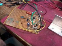
All parts exactly as per Acca's circuit, with manic pairing of every resistor, cap, and transistor.
Problem was we can't get any major brand original darlingtons, so we must to resort to what is locally offered, that is the 10th selection, directly from the trash bin of some unknown chinese manufacturer. Of these was possible to select a half decent complementary pair.
The result was, at the first on a wild oscillation, that was cured with 56pf ceramics (C5-C6). Next was excessive DC offset of 70mA, that was zeroed by R16 in series with VR2.
As we don't dare to apply the full +- 35V supply volts, there was some faint trace of crossing assimetry, that was solved by // R6 - VR3.
Then was time to look at some square wave response, the scope showed a certain ammount of overshoot in the 1000Hz sqw. That was solved, after some trial & error replacing C5-C6 ceramics with a couple of 270pf styroflex, any inferior cap value do not solve the problem.
Now the overshoot is gone, nevertheless the square wave is not exactly squared, presenting some slightly rounded edges, at 100 Hz the SQW was completely scrambled, some serious low frequency limitation.
That was solved by shunting two 100uF to the input cap (the C1-C2-C3 assy)
Now we got nice square wave response at 100, 1000, and 10000 Hz.
1000 Hz SQW rise time 150 usec, response dead flat between 10 and 60 Khz.
+/- 30V supply give clean 18V rms over a 8 ohm dummy load.
Audio was surprising, clean powerful sound, very nice highs, and bass was simply AMAZING, exactly as Acca told.
But then, we got the 4 ohm load test; we were using a variac during the whole test; not even supply rails reach 25V, the darlingtons died, fortunately taking with them only the Variac fuse and nothing more. This occured three times, and we learn that with these shitty transistors You can not apply more than some +/- 18V supply voltage wich ever the load is 4ohm. Not good.
So, by the moment, this promising project is halted until we can resource to some top brand authentic Darlington devices, TIP 142 /47, BDX 32c/34c, or some others that we are not aware, and the fellow forumers can point at.
(* "we" are me, and a friend of mine that got the necessary lab gear, and that knows how to use it. Q3 is BD140)
This is the story of a partial success, or a partial failure, as You like to see it
The road so far:
Inspired by Acca's BDAmp we decided to try the circuit, exactly as showed in the Pee Cee Bee thread (post #1133 - 5th september 2013)
All parts exactly as per Acca's circuit, with manic pairing of every resistor, cap, and transistor.
Problem was we can't get any major brand original darlingtons, so we must to resort to what is locally offered, that is the 10th selection, directly from the trash bin of some unknown chinese manufacturer. Of these was possible to select a half decent complementary pair.
The result was, at the first on a wild oscillation, that was cured with 56pf ceramics (C5-C6). Next was excessive DC offset of 70mA, that was zeroed by R16 in series with VR2.
As we don't dare to apply the full +- 35V supply volts, there was some faint trace of crossing assimetry, that was solved by // R6 - VR3.
Then was time to look at some square wave response, the scope showed a certain ammount of overshoot in the 1000Hz sqw. That was solved, after some trial & error replacing C5-C6 ceramics with a couple of 270pf styroflex, any inferior cap value do not solve the problem.
Now the overshoot is gone, nevertheless the square wave is not exactly squared, presenting some slightly rounded edges, at 100 Hz the SQW was completely scrambled, some serious low frequency limitation.
That was solved by shunting two 100uF to the input cap (the C1-C2-C3 assy)
Now we got nice square wave response at 100, 1000, and 10000 Hz.
1000 Hz SQW rise time 150 usec, response dead flat between 10 and 60 Khz.
+/- 30V supply give clean 18V rms over a 8 ohm dummy load.
Audio was surprising, clean powerful sound, very nice highs, and bass was simply AMAZING, exactly as Acca told.
But then, we got the 4 ohm load test; we were using a variac during the whole test; not even supply rails reach 25V, the darlingtons died, fortunately taking with them only the Variac fuse and nothing more. This occured three times, and we learn that with these shitty transistors You can not apply more than some +/- 18V supply voltage wich ever the load is 4ohm. Not good.
So, by the moment, this promising project is halted until we can resource to some top brand authentic Darlington devices, TIP 142 /47, BDX 32c/34c, or some others that we are not aware, and the fellow forumers can point at.
(* "we" are me, and a friend of mine that got the necessary lab gear, and that knows how to use it. Q3 is BD140)
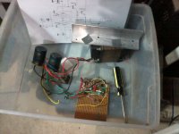
Attachments

Last edited:
Hope you don't mind a couple of comments?
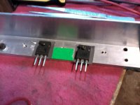
If you use the silpads, DON'T use heatsink grease, it would only make thermal conduction worse. Preferably, don't use silpads, use mica or (better) aluminum oxide insulators. You do need heatsink grease with mica or aluminum oxide, though, even though their thermal conduction is better, they are rigid so the grease is needed to fill the gaps.
Also, are you looking at the idle currents in the outputs during testing? The fuse blowing might be being caused by oscillation, too, if high frequency and strong there would be mutual conduction and a lot of blow-through current!
Hope you don't mind a couple of comments?
Not at all. Any comment and criticism is welcome, I`m here to learn.
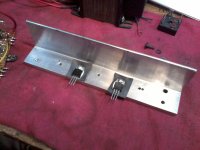
No grease was used with the TIPs
Grease, along with isolation niples, used with no-name BDXs, these blown inmediately.
Cheers
J
you need emitter resistors of .22 to .68 ohms on each output device to limit cross conduction currents.
this?
Attachments
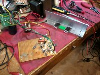
Hi, no, not at the moment in this rat nest layout, but they sure will be in a next revised version (the diodes in thermal contact on the heathsink)How are you tracking the temperature of your heat sink? Are D1-D3 in thermal contact? Maybe a basic Vbe multiplier would be advantageous here.
But we are not experiencing a bias drift issue, but problems with inferior transistors that are not up to the supposed specs
If you search Digikey you will find a good selection of Darlington complimentary pairs to suit your experiment. Darlingtons will run away thermally very quickly if you don't have a good thermal tracking system. I suggest a darlington device on the heatsink as a Vbe multiplier. Emitter resistors in the output stage are a must. I'm surprised your initial design stayed together at all without them.
Good advice. At first I was only looking to reproduce Acca's circuit, exactly as it was presented. His do not use any of these necessary extra parts, nevertheless it works Ok. Sure because He was using some superior quality Darlingtons. He claimed also "zero bias", but that was not possible in my circuit, I believe because I can't apply the 35V "sweet spot" supply voltage, and because my dubious quality Darlingtons.I'm surprised your initial design stayed together at all without them.
When, and if, I finally get my hands on a good reliable darlington pair, along with a proper neat layout, I'm confident I 'll solve the problem and come out with a good stable and reliable circuit.
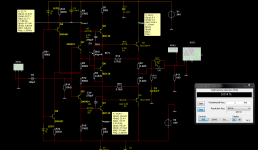
I can not find the return path to gnd for the feedback...some thoughts on the presented circuit
Fab
Ok, very good one. I see that You replaced the diode string by a vbe multiplier, and R11-R12 by active loadssome thoughts on the presented circuit
this is the original that mine is based on:
http://www.diyaudio.com/forums/solid-state/231662-peeceebee-114.html
As You can see Acca is reporting a performance that I was not able to duplicate, note the "3D" rat nest layout, worse than mine. No doubt his BDX 33c/34c are top notch quality.
How are you tracking the temperature of your heat sink? Are D1-D3 in thermal contact? Maybe a basic Vbe multiplier would be advantageous here.
I agree with that.
Similar circuit to my darlington amplifier, you have to pay att. to the thermal stability.
If you can not secure the thermal drift the amplifier will go to self destruction.
Very likely that is why the darlington blew up.

Yes my circuit sound very - very good but I still have the mentioned issue even with VBE.
Attachments
Last edited:
JK excellent! Now to run the simulation I just need Darlington PNP and NPN symbols (.sym) that are not included in the standard LTSpice library
I just made copies of the transistor symbols and renamed them appropriately. I forgot about that since the TIP device models are like sub-circuits and need a symbol associated with them.
EDIT: I attached a ZIP with my symbols, just add them to your LTSpice standard symbols folder.
Attachments
Last edited:
- Status
- This old topic is closed. If you want to reopen this topic, contact a moderator using the "Report Post" button.
- Home
- Amplifiers
- Solid State
- Darlington VSSA