Hi Soren,
I want to design a headphone amp&buffer board.
I'd like to know how to swtich the "headphone/line out" ,and more detail about xfeed.When I switch the "headphone/line out" is any difference on L/R output?
And when dam1941 swtich on headphone mode,is it possible to be too loud?
I want to design a headphone amp&buffer board.
I'd like to know how to swtich the "headphone/line out" ,and more detail about xfeed.When I switch the "headphone/line out" is any difference on L/R output?
And when dam1941 swtich on headphone mode,is it possible to be too loud?
1) Yes, the dam1941 itself is 350 mA max, per manual.
2) The only active parts on the buffer board are the opamps, and you can use whatever you want there....
3) No isolation there, the serial port is designed to only be used for settings and firmware upgrades.
Søren,
- I was planning on creating my own user interface board that has it’s own microcontroller on it. One of the things i want to so is to add an OLED display to it.
- I’m willing to sign an nda, but would it be possible to get the code of the current controller?
- Also, if I would add an isolator chip, would it be possible to use the serial port for the interaction wth the microcontroller?
I think the code would help in understanding how to use a remote control with your display board. That isn’t documened. The IR receiver (U9) is also not documented in the display board schema it seems, or am i missing something here?
Last edited:
Hi Soren,
Could you please, enlighten me a little about the following (from the manual of 1941 page 6):
(in few words, what exactly should we pay attention to ?)
Also, could I power the VCC5D with separate (super capacitors) PSU, which will completely different unit that the one for analog power ?
Thank you in advance and have a nice evening.
Could you please, enlighten me a little about the following (from the manual of 1941 page 6):
(in few words, what exactly should we pay attention to ?)
There is no requirement for specific ramp up/down, although to avoid DC voltage on the outputs all power pins should ramp up and down within 0.5 sec of each other.
Also, could I power the VCC5D with separate (super capacitors) PSU, which will completely different unit that the one for analog power ?
Thank you in advance and have a nice evening.
Black Friday and Cyber Monday Specials
From Friday Nov 23, 2018 to Monday Nov 26, 2018 we're having a special discount of 15% on the dac1421, dac1541, dam1921 and dam1941. See Soekris Engineering ApS, Ordering for information about where to take advantage of this special offer.
From Friday Nov 23, 2018 to Monday Nov 26, 2018 we're having a special discount of 15% on the dac1421, dac1541, dam1921 and dam1941. See Soekris Engineering ApS, Ordering for information about where to take advantage of this special offer.
Hey Soren,
Thrilled that you have new products in the DIY line! I've been in touch with your new US vendor and he said he could order DAM1941 from you but seems uncertain about the accessory boards. Do you have any plans to release the boards separate?
Also, with the parts listed in the BOM, what kind of improvements would the buffer board(1961) have compared to dam1021 v4/v5 dual mono buffered output? This might be a pretty basic question but hopefully some others are curious about it too!
Thanks!
Michael
Hey Soren,
Thrilled that you have new products in the DIY line! I've been in touch with your new US vendor and he said he could order DAM1941 from you but seems uncertain about the accessory boards. Do you have any plans to release the boards separate?
Accessory boards are in stock, can't see any problems....
The boards are pretty low cost, so I'm not interested in the logistics in selling them separately....
[/QUOTE]
Also, with the parts listed in the BOM, what kind of improvements would the buffer board(1961) have compared to dam1021 v4/v5 dual mono buffered output? This might be a pretty basic question but hopefully some others are curious about it too!
Thanks!
Michael[/QUOTE]
The buf1961 buffer Board is basically just a bunch of opamps, but you can choose what opamps to use.... Most opamps are so8 package nowadays, but as the buf1961 also have dip8 footprint you can buy a bunch of so8 to dip8 adapters and try different opamps....
I'm hoping to get some feedback how different technologies sound to people, like the TI cmos opa1678, jfet opa1642 and bipolar opa1602 (used on the dam1021), they're all rail-rail output so they can run on just +-5V.
Hi Soren,
I want to design a headphone amp&buffer board.
I'd like to know how to swtich the "headphone/line out" ,and more detail about xfeed.When I switch the "headphone/line out" is any difference on L/R output?
And when dam1941 swtich on headphone mode,is it possible to be too loud?
I'll update the manual soon with more details on the switching. If implemented as I will describe, the switching is smooth.
Interested in purchasing a DAM1941 for Cyber Monday, but none of the accessory boards are available at Mod House Audio. Is that an error? Will they be available at a later date?
Interested in purchasing a DAM1941 for Cyber Monday, but none of the accessory boards are available at Mod House Audio. Is that an error? Will they be available at a later date?
Seems to be up now ?
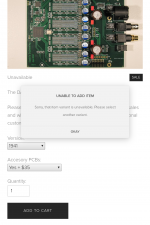
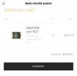
The DAM1941 is available if "No" is selected for "Accessory PCBs". Price is $549 and I'm able to add it to my cart.
But if "Yes + $35" is selected for "Accessory PCBs" then the DAM1941 is shown as unavailable.
See attached screenshots.
But if "Yes + $35" is selected for "Accessory PCBs" then the DAM1941 is shown as unavailable.
See attached screenshots.
Attachments
Søren,
Built the psu accessory board today and noticed that the silk screen for the extra power connector (the one to the buffer board) is incorrect.
Somehow the GND and voltage outputs are switched.
The schema in your manuals is correct.
Built the psu accessory board today and noticed that the silk screen for the extra power connector (the one to the buffer board) is incorrect.
Somehow the GND and voltage outputs are switched.
The schema in your manuals is correct.
Søren,
Built the psu accessory board today and noticed that the silk screen for the extra power connector (the one to the buffer board) is incorrect.
Somehow the GND and voltage outputs are switched.
The schema in your manuals is correct.
Yes, small error on PCB silkscreen. Manual is correct.
Unfortunately I have missed black friday and cyber monday ... is there another action in the next days or before christmas?
best, Peter
best, Peter
Unfortunately I have missed black friday and cyber monday ... is there another action in the next days or before christmas?
best, Peter
I'm not planning any.
As I see in the description and on the pictures is an IR receiver on the user interface board ... with which remote control can you operate the board?
Best regards, Peter
Best regards, Peter
As I see in the description and on the pictures is an IR receiver on the user interface board ... with which remote control can you operate the board?
Best regards, Peter
The remote interface works with a Apple Remote, just like a dac1541, see that manual for details.
Søren,
My dsp1971 board is malfunctioning.
No single led lights and the three display modules statically indicate -88.
The dac responds to the rotary encoder but i have not tested the ir receiver yet.
The individual leds and resistors are ok, tested with a separate 5v supply with the dsp board disconnected.
So i’m guessing i must have damaged one of the shift registers during soldering, would you have any other ideas or clues?
Thanks!
Good morning, when I looked at the schematics of the additional boards yesterday, I noticed the unusual design of the power supply. The upper part is clear, the lower part is not. Why did you put the capacitors in front of the rectifier? I have not seen that yet ...
- Home
- Vendor's Bazaar
- dam1941 - Next Gen Discrete R-2R Sign Magnitude 24 bit 384 kHz DAC module