Website brightnoise.nl will be closed on 2015 April 6. There is apparently little interest in DAC settling errors, loudspeaker current driving and problems with ANY mathematical multiplication (plus its errors!) in digital chains without dither at ALL the quantization steps, i.e. word length limitation. This ranges from a simple volume control in the digital domain up to the addition of all the signal components in a FIR filter. I am a little bit disappointed in the majority of people following some guru's and missing the essential points in sound signal processing and reproduction. Frustration? No, I continue without public! frans(AT)sessink.nl
Website brightnoise.nl will be closed on 2015 April 6. There is apparently little interest in DAC settling errors, loudspeaker current driving and problems with ANY mathematical multiplication (plus its errors!) in digital chains without dither at ALL the quantization steps, i.e. word length limitation. This ranges from a simple volume control in the digital domain up to the addition of all the signal components in a FIR filter. I am a little bit disappointed in the majority of people following some guru's and missing the essential points in sound signal processing and reproduction. Frustration? No, I continue without public! frans(AT)sessink.nl
Hi, Frans,
I've just now discovered this thread and and read some of your brightnoise.nl documents. I have a couple of questions regarding your SES concept.
1) Don't most DAC chips already integrate a Sample & Hold circuit to de-glitch the final output? Wouldn't that de-glitching circuit provide essentially the settling time error rejection benefits as your SES concept?
2) Do you see DAC chips based on switched active current sources as avoiding the problems caused by a fixed slew rate driving a shunt capacitance? With switched active current sources, it would seem that the slew rate in to a given shunt capacitance would scale proportionally with output signal current level. Similar to how it does for an RC based slewing function, except for exhibiting a linear slope rather than an exponential curve.
Last edited:
Exponential settling in DAC
Ken, deglitching can indeed be done with a sample-hold, but what I have seen in these existing deglitching circuits is different from clean exponential settling. And your second point: slew-rate overload is, for input signals stronger than where the slew-rate starts, almost independent from that input overload.
So answers on both questions is no. Further: a sample-hold added after an existing DAC must be free from slew-rate effects. Exponential settling is IMHO the only way to get rid of signal-level dependent delay.
Rgds, Frans Sessink
Frans, I will give the implications of DAC settling time a bit more thought as a result of your work. Thanks, for sharing.
Hi, Frans,
Another question if I may, as I'm genuinely interested in understanding the system implications of your proposed settling time solution. Since all active circuits have some finite slew rate limit, doesn't the use of an external sample-and-hold circuit, whether implemented by analog switch and hold capacitor or by S-H amplifier IC, only transfer the slew rate limiting issue from the DAC to the external active S-H circuit?
Another question if I may, as I'm genuinely interested in understanding the system implications of your proposed settling time solution. Since all active circuits have some finite slew rate limit, doesn't the use of an external sample-and-hold circuit, whether implemented by analog switch and hold capacitor or by S-H amplifier IC, only transfer the slew rate limiting issue from the DAC to the external active S-H circuit?
Last edited:
Thank you Frans for the very interesting information. I think I understood pretty well the problem you are exposing (in my words, the dac settling is not well behaved, not consistent - it varies with code / step size).
Therefore, implementing the sample and hold with a 4066 switch that is switched on at the appropriate time (near the "middle" of the sample would surely be enough for non oversampled systems), and stays on only for the (short) amount of time required to charge the small capacitors, looks indeed like an interesting solution. It is completely replacing the dynamic behaviour of the dac with the one of the sample and hold circuit.
I´m not all that familiar with the 4066 switch, I´m looking at the datasheet right now, I´d like to understand what are the limitations with this choice of part, in this application. Is there possibility of an improvement with discrete sample and hold?
Is the on-resistance of the switch of any concern here? Does it vary with current? You are limiting the current with 1K series resistor, so the variation of Ron of the switch must be small enough compared to this 1K.
Again thanks for the information Frans, I will surely build the sample and hold with 4066 for my tda1543 dac. Since I have the clock in the dac, and a CPLD, I can easily generate the sampling pulse.
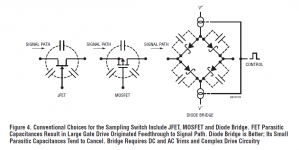
Designing a good sounding sample/hold isn't trivial. You have to watch out for digital - analog crosstalk - I'd not necessarily choose the 4066 initially as I don't see its designed with low crosstalk in mind. Rather its really a digital part. I seem to recall from a textbook I have that for S/H a bridge of diodes might be a more optimum choice - I will investigate which book that was. Added to this TDA1543 has poor low-level linearity to begin with so wouldn't it be better to begin with a more ideal DAC?
Hi Richard!
Yes, I was thinking right now that the TDA1545 is the right part for this project. Or maybe AD1862. I recall you saying these are glitchy. The sample and hold would be just right for them.
Have you tried any S/H circuits?
Yes, I was thinking right now that the TDA1545 is the right part for this project. Or maybe AD1862. I recall you saying these are glitchy. The sample and hold would be just right for them.
Have you tried any S/H circuits?
Hi Alex - good to see you back here again 🙂
We were both thinking alike, I'd say a CMOS DAC is precisely the kind of DAC that may well benefit from deglitching. The glitches on the TDA1545 come from the power supply though, via the internal current source rather than inherently from the DAC architecture. So perhaps even better to add a S/H to an R2R kind of DAC where the switch mis-timings add glitches. PCM63 maybe since that one has a strong following for good SQ to begin with. Or yes, AD1862 - I seem to recall seeing the output looked rather glitchy at mid-scale.
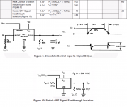
No, I've never tried a S/H but often thought about implementing one which was when I discovered the ring of diodes solution. You might find inspiration from Jim Williams' writings on measuring DAC settling time - he needed a kind of analog switch with very low feedthrough and in the end went with an OTA. The paper is here : http://cds.linear.com/docs/en/application-note/an120f.pdf
We were both thinking alike, I'd say a CMOS DAC is precisely the kind of DAC that may well benefit from deglitching. The glitches on the TDA1545 come from the power supply though, via the internal current source rather than inherently from the DAC architecture. So perhaps even better to add a S/H to an R2R kind of DAC where the switch mis-timings add glitches. PCM63 maybe since that one has a strong following for good SQ to begin with. Or yes, AD1862 - I seem to recall seeing the output looked rather glitchy at mid-scale.
No, I've never tried a S/H but often thought about implementing one which was when I discovered the ring of diodes solution. You might find inspiration from Jim Williams' writings on measuring DAC settling time - he needed a kind of analog switch with very low feedthrough and in the end went with an OTA. The paper is here : http://cds.linear.com/docs/en/application-note/an120f.pdf
Last edited:
In doing DAC development its important I feel to attack problems that really make a difference to the SQ. So much of the time in audio problems are attacked before ascertaining that solving them is going to make for an audible improvement. In the case of implementing a S/H I don't know what audible deficiency it might fix up - perhaps improve dynamics but I've found dynamics are still mostly limited by the amp I'm using. Hence working on amps takes priority over DACs, until I reckon I've gotten an amp which beats my DAC.....
I agree Richard, SQ is the goal and we have to fix the bigger problems first, of course. I haven´t really fixed my amp yet. And the signal I feed to it sure needs BW limiting, but the cap to ground doesn´t cut it with tda1543 - remember we talked about it? Sounds worse to me. Could this be the cause (the issue explained by Frans, variable settling time)? I think the cap would not be providing the desired exponential settling, if there are settling time variations.
I've forgotten who I discussed what with nowadays 🙂 But yes I found that the cap to ground sounded worse with TDA1543. I doubt that settling time is the cause though - adding a cap certainly slows down settling time but is going to make it more consistent by swamping the variable output capacitance of the DAC itself. So overall no change. What I suspect may be happening with caps to ground is they induce glitching on the power supply. That tentative conclusion's based on thinking about why an opamp used as I/V sounds best with no capacitance across the feedback resistor - even though theory says we should use the cap to prevent slewrate limiting in the opamp. Caps on the output of DACs (I got this effect recently on the TDA1387 I'm listening to right now) are bad news all round - use a series inductor then the cap or no cap at all.
I doubt measurements will indicate some figure that correlates well with how it sounds.
Still want to try with 4066 for the switches? I just looked at the original CMOS version of these switches (CD4066) and it explicitly said in the DS that for S/H applications the CD4016 was recommended. The 4016 has lower coupling capacitance (but also higher on-resistance). Also worth looking at CD4007 for a more 'discrete' version of a CMOS switch.
Still want to try with 4066 for the switches? I just looked at the original CMOS version of these switches (CD4066) and it explicitly said in the DS that for S/H applications the CD4016 was recommended. The 4016 has lower coupling capacitance (but also higher on-resistance). Also worth looking at CD4007 for a more 'discrete' version of a CMOS switch.
Thanks Richard, I´ll take a look. Not sure if I´ll build it anytime soon, but I am certainly curious about how it would sound.
S/H
I found interesting your web site and measures I found on them .
Please can you see my thread , and what do you thinking about ?
http://www.diyaudio.com/forums/lounge/270011-shannon-ad-fc-2-tricks.html
I found interesting your web site and measures I found on them .
Please can you see my thread , and what do you thinking about ?
http://www.diyaudio.com/forums/lounge/270011-shannon-ad-fc-2-tricks.html
Conversions tricks
I found more interesting the site with the fft measures .
Please read my thread at last my complete example and if you have found a solutions to increase precision on cancellation by an S/H techniques .
Complete example at post 91
http://www.diyaudio.com/forums/lounge/270011-shannon-ad-fc-2-tricks.html
Laszlo,
the settling speed of a flash DAC depends on the actual binary value at the input. The number of current sources that is active to generate the (corresponding to the binary word) output current varies from word to word. The output capacitance is in this way modulated and so is the settling time.
The settling time of a TDA1543 is specified as "within 500 ns". The measured settling time shows variations in the tens of nanoseconds, depending on the actual value at the output. So the DAC modulates the signal delay from sample to sample. My conclusion is that the influence of this stochastic group delay modulation is higher than the jitter from a good clock, like the Tent-lab clocks.
This "modulated capacitance" is probably an explanation for the sound differences as a function of the load impedance of a DAC with current-output.
The varying capacitance problem can be solved with a proper I-to-V converter. Most op-amps can not handle the fast settling of the DAC current and will introduce a slew-rate limitation. Also the DAC itself has internally a slew-rate limitation. (My DAC is a single TDA1543).
*****
There is however a simple solution for the DAC settling problem errors. The solution combines the settling-induced errors and the exact timing of the output samples (the jitter problem). The circuit is very simple and understanding that solution does not require a university degree or special education.
Explanation in simple words: the DAC output signal is sampled AFTER full settling. In this way the accuracy of the signal level is almost as good as a static (DC) DAC conversion. The sample-hold is clocked by a synchronized recovered clock that solely determines the timing of the output signal (or jitter). The sample-hold settling is free from slew-rate limitation and settles as an RC-delay (constant group delay; no signal-dependent variations). And also part of the system is an I-to-V converter with an op-amp. The slew-rate limitation of this I-to-V converter is not affecting the audio quality in this design, since the sample-hold is taking a sample later-on in time, after final settling of this suspicious signal processing element.
What can be done more in a NOS-DAC than this: output the correct sample value at the correct moment and remove the stochastic variable group delay?
The system is described on frans.sessink.nl or www.brightnoise.nl and is already available on the internet for months.
The name for the combination of the two ingredients:
Synchronized Exponential Settling NOS DAC
Stereo is back again without the scratches, the limited channel separation, the limited frequency response and the rumble, the hum and the noise from vinyl.
Enjoy!
Frans Sessink
I found more interesting the site with the fft measures .
Please read my thread at last my complete example and if you have found a solutions to increase precision on cancellation by an S/H techniques .
Complete example at post 91
http://www.diyaudio.com/forums/lounge/270011-shannon-ad-fc-2-tricks.html
Last edited:
- Status
- Not open for further replies.
- Home
- Source & Line
- Digital Source
- DAC Settling Time