Richard, the paper by Jim Williams is a very very interesting read. Thanks again.
I´d like to quote:
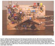
"The measurement results presented in this publication
required painstaking care in breadboarding, layout and
connection techniques. Wideband, 10μV resolution
measurement does not tolerate cavalier laboratory attitude.
The oscilloscope photographs presented, devoid
of ringing, hops, spikes and similar aberrations, are the
result of an exhaustive (and frustrating) breadboarding
exercise1. The breadboard was rebuilt numerous times
and required weeks of layout and shielding experimentation
before obtaining a noise/uncertainty fl oor worthy of
20-bit measurement. In particular, extreme measures were
required to minimize sample command signal feedthrough.
Layout techniques include minimization and restriction of
radiative paths, ground plane current management and
mounting the LT1228 “switch” upside down, allowing its
V-referred substrate to approximate a monolithic shield
for the IC’s internal circuitry."
http://cds.linear.com/docs/en/application-note/an120f.pdf
I´d like to quote:
"The measurement results presented in this publication
required painstaking care in breadboarding, layout and
connection techniques. Wideband, 10μV resolution
measurement does not tolerate cavalier laboratory attitude.
The oscilloscope photographs presented, devoid
of ringing, hops, spikes and similar aberrations, are the
result of an exhaustive (and frustrating) breadboarding
exercise1. The breadboard was rebuilt numerous times
and required weeks of layout and shielding experimentation
before obtaining a noise/uncertainty fl oor worthy of
20-bit measurement. In particular, extreme measures were
required to minimize sample command signal feedthrough.
Layout techniques include minimization and restriction of
radiative paths, ground plane current management and
mounting the LT1228 “switch” upside down, allowing its
V-referred substrate to approximate a monolithic shield
for the IC’s internal circuitry."
http://cds.linear.com/docs/en/application-note/an120f.pdf
Attachments
Last edited:
Nice paper
It possible use this principle to "re clocking" samples on output of all types of dac .
On Dac that use a linear interpolation such as tda1343 there isen't a stable value on
output for every sample.
Richard, the paper by Jim Williams is a very very interesting read. Thanks again.
I´d like to quote:
"The measurement results presented in this publication
required painstaking care in breadboarding, layout and
connection techniques. Wideband, 10μV resolution
measurement does not tolerate cavalier laboratory attitude.
The oscilloscope photographs presented, devoid
of ringing, hops, spikes and similar aberrations, are the
result of an exhaustive (and frustrating) breadboarding
exercise1. The breadboard was rebuilt numerous times
and required weeks of layout and shielding experimentation
before obtaining a noise/uncertainty fl oor worthy of
20-bit measurement. In particular, extreme measures were
required to minimize sample command signal feedthrough.
Layout techniques include minimization and restriction of
radiative paths, ground plane current management and
mounting the LT1228 “switch” upside down, allowing its
V-referred substrate to approximate a monolithic shield
for the IC’s internal circuitry."
http://cds.linear.com/docs/en/application-note/an120f.pdf
It possible use this principle to "re clocking" samples on output of all types of dac .
On Dac that use a linear interpolation such as tda1343 there isen't a stable value on
output for every sample.
IF the OP is correct about DAC settling problems (variable with code, non-exponential) and I have no reason to think he´s wrong, then the sampling switch does look like a very good idea, altough hard to implement. It must be hard to achieve the desired low noise and low glitch operation. This is very advanced stuff imo.
Applications
I think that problem is very important on particular freq inside Shannon band fc/2
for example 15Khz nearest fc/3 . At this fo the samples made a 2 sine waves with
opposite phase under digital domain they are invisible but when the signal going
out on dac is possible a big stress for it .
Please see my thread
http://www.diyaudio.com/forums/lounge/270011-shannon-ad-fc-2-tricks-10.html#post4243985
Go to post 91 and made example .
I don't have an anlog fft analyzer and the "re clocking" to see setling time .
But if you can made a tests on one or more type of a DAC
I'm interesting what's happen at settling time when going from
+Vmax (sample n) -Vmax (sample n+1)
Please post results .
IF the OP is correct about DAC settling problems (variable with code, non-exponential) and I have no reason to think he´s wrong, then the sampling switch does look like a very good idea, altough hard to implement. It must be hard to achieve the desired low noise and low glitch operation. This is very advanced stuff imo.
I think that problem is very important on particular freq inside Shannon band fc/2
for example 15Khz nearest fc/3 . At this fo the samples made a 2 sine waves with
opposite phase under digital domain they are invisible but when the signal going
out on dac is possible a big stress for it .
Please see my thread
http://www.diyaudio.com/forums/lounge/270011-shannon-ad-fc-2-tricks-10.html#post4243985
Go to post 91 and made example .
I don't have an anlog fft analyzer and the "re clocking" to see setling time .
But if you can made a tests on one or more type of a DAC
I'm interesting what's happen at settling time when going from
+Vmax (sample n) -Vmax (sample n+1)
Please post results .
Last edited:
Yes, measurements would be interesting. My DSO is broken.
I just dig up a settling time measurement of my AD1865 + common base I/V stage. It´s a 20khz square wave. IF you look closely the settling time is clearly different for the falling and rising edge, actually the "knees" all look a bit different. Doesn´t tell much. There is clearly noise and maybe a low level oscillation riding on the signal.
I just dig up a settling time measurement of my AD1865 + common base I/V stage. It´s a 20khz square wave. IF you look closely the settling time is clearly different for the falling and rising edge, actually the "knees" all look a bit different. Doesn´t tell much. There is clearly noise and maybe a low level oscillation riding on the signal.
Attachments
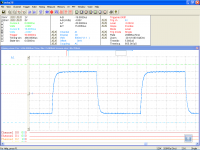
That dso was pretty capable in time resolution. Analog BW 100MHz and sampling 200MS/s. The settings above say there were 1000 samples per division! I should have saved the waveform data to zoom in and analyse. Instead I only made screen capture. Vertical resolution was poor: 8 bits and the lsb was noisy always. Still very useful, but gone beyond repair now.
I recall that I made these measurements using a protoboard! No ground plane, nothing soldered. Just having some fun. They would have been a million times cleaner with dead bug technique over solid ground plane. Which is how I plan to do my next dac. (After I fix my lm3886 amp psu. I will make it regulated and with quite a bit of capacitance AFTER the regulators!)
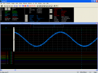
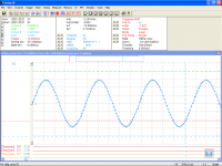
Here's passive i/v versus common base i/v. 1KHz sine. Very different levels.
Here's passive i/v versus common base i/v. 1KHz sine. Very different levels.
Attachments
Non ideal of dac
I think the non ideal conversion from digital to analog can made visible the 2 signals
sinusoidal result of modulation of the samples at 15Khz.
If dac is nearest an ideal the median of modulation run to zero .
If the dac as far from ideal the median of modulation become a new sine signal added to
the original 15KHz sine but at low frequencies .
In the end is so difficult to evaluated THD of this type of noise it disturb others sine
components of complex signal .
The main error become from settling time i think and the slew rate of I/V converter .
On you interesting measures is an evidence about this fact (is possible to see the
small errors)
A measurement of a pure sine at 15Khz or neares to the fc/3 ( when dac works with a
samplerate of 44100Hz ) make possible to evaluated quality of a dac .
On fft this component of noise on a good dac are down to -60dB .
But the ear are a good fft analyzer
Last edited:
Architectures
Do you think is a good o bad idea to put the ouput of 2 identical dac one on I/V inverted
and the second on a I/V non inverted .
Ok the time rise and time fall are different but if i use the dac in the same phase and put
outputs in opposite phase the cancellation run to a best value or not ?
Do you think is a good o bad idea to put the ouput of 2 identical dac one on I/V inverted
and the second on a I/V non inverted .
Ok the time rise and time fall are different but if i use the dac in the same phase and put
outputs in opposite phase the cancellation run to a best value or not ?
I don´t know, I put some thought into it and I fail to understand what cancellation you would like to achieve with that config. Other than averaging two dacs and having a balanced out. Could you explain?
On the other hand, a dual dac in anti-phase looks very interesting to me. With identical IVs. Some reasons:
-averaging between two dacs, like paralleling
-like you said, different rise and fall times are a source of error. So if the input to one I/V is rising and the other is falling you should get some cancellation of that error, I think.
-nearly constant current on the analog supply pins of the dac, except for glitches that are different between phases and imbalances. A constant current on these pins is good for a number of reasons. Smaller transient currents circulating through the parasitics of the circuit.
Well, the constant current thing I have never measured, I would like to see if there´s really an advantage in that sense but I need to buy a new scope first. And that´s not happening too soon I´m afraid🙁
Not be afraid
For project a new dac is needed many months .
I haven't a last type of scope with a good fft .
We are in the same situation, but the learning what is a possible solution need many
time.
For project a new dac is needed many months .
I haven't a last type of scope with a good fft .
We are in the same situation, but the learning what is a possible solution need many
time.
Over on Head-fi the designer of the latest flagship Schitt DAC (Yggy) has mentioned which DAC chip he's using (not an audio one) and also says he addressed glitching problems. Here's his post : Thoughts on a bunch of DACs (and why I hate chocolate ice cream) - Page 193
Conversion
Ok but dac is only one part of all conversion circuit .
+-1 lsb and 1ppm is a primate for dac's but all others parts need to more good than dac .
Ok but dac is only one part of all conversion circuit .
+-1 lsb and 1ppm is a primate for dac's but all others parts need to more good than dac .
Yes I agree - a headline figure for a DAC of 20bits looks to be only valid for very low frequencies. In audio this DAC looks to be well below 20bits - for example the THD @ 1kHz is -97dB at 10kHz sample rate. Imagine how much worse it gets at 176kHz (for 4X OS). Even the TDA1541A which has a settling time of 500nS to 16bits degrades in THD+N by 2dB going from 4X OS to 8X OS.
It is curious how he overcome glitchs ,he saids SHA is ***.
On the other hand,it is able to adjust TDA1541A's glitch. Nakamichi did it.
http://www.diyaudio.com/forums/digi...e-nos-dac-using-tda1541a-492.html#post3616945
http://www.diyaudio.com/forums/digi...e-nos-dac-using-tda1541a-497.html#post3734169
On the other hand,it is able to adjust TDA1541A's glitch. Nakamichi did it.
http://www.diyaudio.com/forums/digi...e-nos-dac-using-tda1541a-492.html#post3616945
http://www.diyaudio.com/forums/digi...e-nos-dac-using-tda1541a-497.html#post3734169
Settling time and thd
I think the setling time is very important ven sine on input is nearest 15khz see my thread
http://www.diyaudio.com/forums/lounge/270011-shannon-ad-fc-2-tricks.html
going on post 91.
But is so difficult to concrete estimate the increase of audio quality because the signals on
output an non ideal dac , the THD measure fail with this case i think...
oversample 4x is a limit overall .
Small settling time
If we run at 4X oversampling the time is nearest 5.8us .
A smallest settling time is the 2% of the samplerate time .
It becomes nearest 117ns this meanes you need a very fast dac
If we run at 4X oversampling the time is nearest 5.8us .
A smallest settling time is the 2% of the samplerate time .
It becomes nearest 117ns this meanes you need a very fast dac
Settling time
The datasheet report settling time only if one LSB is changed for example
TDA1545 +-1LSB have a settling time 0.2us (medium value)
But was happen when changing more than one bit .
Nos architectures have many reasons to exist .
The datasheet report settling time only if one LSB is changed for example
TDA1545 +-1LSB have a settling time 0.2us (medium value)
But was happen when changing more than one bit .
Nos architectures have many reasons to exist .
If the settling time is reported for only 1LSB change that's a fairly useless specification. But the ADI DAC Schitt uses isn't specified for such a small change - 500LSBs is one figure.
Yes NOS I believe sounds good for the reason of the DAC being at the right value for a greater proportion of the time.
Yes NOS I believe sounds good for the reason of the DAC being at the right value for a greater proportion of the time.
- Status
- Not open for further replies.
- Home
- Source & Line
- Digital Source
- DAC Settling Time