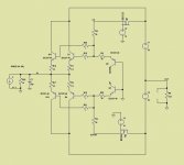
Yes, Patrick, on the surface it looks like the Leach but the bias transistors do something different.
I'm afraid it won't work the way you intend. It work with low distortion in my circuit because don't have voltage variations in the input transistors. the cen topology unfortunately have voltage variation in the input transistors.
A cascode would help.
Patrick
I think so. but we have to take care of the base currents of the cascade. The final circuit will be more complex that your version of the cen.
I made a mistake.I think the distortion is caused by Cob and Zout of Q1/Q4/Q13/Q14 ,not base current.
not Q1/Q4/Q13/Q14,but Q2 and Q5.
then,the distortion will reduce with bootstraping their collector.
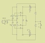
At the cost of some complexity it could be a voltgae in - current out mirror but then we come closer to component count of the original design.
I think the distortion is caused by Cob and Zout of Q1/Q4/Q13/Q14 ,not base current.
Forgot to say that you right 😉

I made a mistake.
not Q1/Q4/Q13/Q14,but Q2 and Q5.
then,the distortion will reduce with bootstraping their collector.
Do a simulation. IM with a Android phone only don't have my computer. And post your results .
Dirkwright it works but not with the very low distortion that my circuit is capable. Joachim wants to achieve my distortion levels with the simplicity of the
cen topology
cen topology
Dirkwright it works but not with the very low distortion that my circuit is capable. Joachim wants to achieve my distortion levels with the simplicity of the
cen topology
Well, it's just a matter of a tweek here and a tweek over there. I just wanted to show that it wasn't an oscillator. I'm just trying to help out.
At the cost of some complexity it could be a voltgae in - current out mirror but then we come closer to component count of the original design.
Yes. And start to make no sense.
I would be happy with -100dB, but anyway. It all feels so familiar to me. Malkolm told me in the old days that I/U converters and MC inputs can have a lot in common.
I have virtually no experience with I/U converters for digital though.
I have virtually no experience with I/U converters for digital though.
Well, it's just a matter of a tweek here and a tweek over there. I just wanted to show that it wasn't an oscillator. I'm just trying to help out.
It seems a stable circuit . Its strange to give problems to Joachim.
I would be happy with -100dB, but anyway. It all feels so familiar to me. Malkolm told me in the old days that I/U converters and MC inputs can have a lot in common.
I have virtually no experience with I/U converters for digital though.
How much current a MC produce ? What is the gain you need?
Optimal is a gain of 20x to 30x ( 26dB ), the cartridge i have has a DC impedance of 6 Ohm and puts out 0.5mV nominal. Because some records are cut hot ( plus 20dB ) and there is dirt and cracks on the record it can put out more then 10mV pulses, especially at higher frequencies.
that is very low. you shold be fine with the simple circuit that you construct. its stranje to have problems. if possible post the shema that you use. just to better visualization.
- Home
- Source & Line
- Digital Source
- dac I/V convertion with very low distortion