Something practical. LowDist I/V MC nearly ready.
Hope it don´t end up to be a oscillator, you have to slow it down, do not forget.
Yes, the circuit i build makes some trouble. I have one or two ideas to try though.
I will publish what i have at the moment. Maybe somebody has an idea how it can be made to work.
I will publish what i have at the moment. Maybe somebody has an idea how it can be made to work.
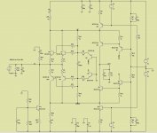
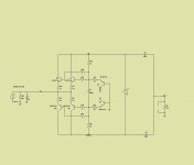
I have decided to follow Calvin suggestion of using a current source to cancel the dac offset current.
The current offset and dc out is now control by a R29 (that will be a 1k resistor in serie with 1k potentiometer ).
I have added C8/R25 C10/R26 C4/R24 for stability.
And now every thing seems to be very stable, the most sensible nodes are the nodes named UP and DOWN.
If you wish, the input zobel can be omited, but i keep them, because i feel it add stability.
The main current sources ware also changed (v5 and V4 will be two green led in serie).
Attachments
Yes, the circuit i build makes some trouble. I have one or two ideas to try though.
I will publish what i have at the moment. Maybe somebody has an idea how it can be made to work.
What type of troubles ?
I will be glad to help if i can.
I start already to make the pcb for the circuit above.
I bassically build your input stage but with a floating single supply like the Zen,Cen.
Ether the circuit does not work this way and needs a plus-minus supply or i have problems with stability. The scope shows some wild waveforms.
Ether the circuit does not work this way and needs a plus-minus supply or i have problems with stability. The scope shows some wild waveforms.
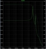
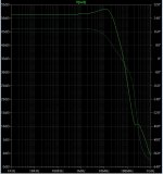
Below are the frequency response of the circuit before the modifications and after.
As you see the old version start to misbehave above 20Mhz With two enormous peaks at 33Mhz and 88Mhz .
The new version has a much stable frequency response
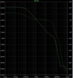
Note that this frequency response are measure without the output capacitor C1. The last figure is the response with the output capacitor.
As you see the old version start to misbehave above 20Mhz With two enormous peaks at 33Mhz and 88Mhz .
The new version has a much stable frequency response
Note that this frequency response are measure without the output capacitor C1. The last figure is the response with the output capacitor.
Attachments
I bassically build your input stage but with a floating single supply like the Zen,Cen.
Ether the circuit does not work this way and needs a plus-minus supply or i have problems with stability. The scope shows some wild waveforms.
if you post a schema maybe i can help.
Edit: I have to take a better look to the sen/cen circuit as it seems are a lot of people interested.
If i understand you . you change the jfets by the bjt´s.
Last edited:
Yes, that is the circuit. I reduced R13, R14 to 2kOhm and put a ballast resistor after the electrolytics of 220 Ohm. The electrolytics are 470uF Nichicon bipolar.
should you not gnd the transistors for the base currents to get a GND lock on it somewhere...??
should you not gnd the transistors for the base currents to get a GND lock on it somewhere...??
it was an error i already delete the posts.
I think the distortion is caused by Cob and Zout of Q1/Q4/Q13/Q14 ,not base current.
You have to make the voltage stable in the up and down nodes if you want to achieve very low distortion, i think i know how to do that, but today i have no time. Next week.
Joachim,
Re post #208, you are basically back to the original Leach design :
Moving Coil Cartridge Head Amps
With all its pro's and con's.
Cheer,
Patrick
Re post #208, you are basically back to the original Leach design :
Moving Coil Cartridge Head Amps
With all its pro's and con's.
Cheer,
Patrick
Yes, Patrick, on the surface it looks like the Leach but the bias transistors do something different.
The bias transistor is like that of Hawksford, right ?
http://www.diyaudio.com/forums/digital-source/168093-hawksford-discrete-iv-twist.html
Patrick
http://www.diyaudio.com/forums/digital-source/168093-hawksford-discrete-iv-twist.html
Patrick
The Hawsford is more complex i think. Q2 is tied to the supply and Q3 feeds back ( forward ? ) to the input transistor.
As i see circuit pots 208 the bias transistors sense the base current of the input transistors and add them to the other polarity of the output.
In the Leach the bases of the input transistors are simply held on a constant potential.
I use an optimized Leach input stage in my Nobrainer Phono. That does not have a floating supply though and filters and clamps the base current of the input transistors to ground for a 3dB noise advantage. Here the big electrolytic does that job.
- Home
- Source & Line
- Digital Source
- dac I/V convertion with very low distortion