It is great to see all the different routes to getting your own preferred sound or whatever your goal is. The i/v issue with the DAC chip characteristics is the main issue. Everything else pails. The waxing lyrical over old DAC chips is interesting as with progress a past favourite suddenly becomes yesterdays coffee. The construction of chip has moved forward a long way. Not only in terms of designed peformance but the basic way RLC is incorporated in the chip.
For my money, how can the host of old chips match the raw capability of the best modern 130dB+ SNR chips used to their capability. The only way we can keep up is by making new dacs as the new designs come along with new Eurika moments. Its great fun and keeps us DIYers busy
For my money, how can the host of old chips match the raw capability of the best modern 130dB+ SNR chips used to their capability. The only way we can keep up is by making new dacs as the new designs come along with new Eurika moments. Its great fun and keeps us DIYers busy
Last edited:
If I recognize correctly, that may be soviet or russian helipot.What is this component (circled in red) ? I've never seen anything like that before.

Not everybody agrees about Lundahls but prefer cap output. An analogue stage that can be left out is always good news, whether valve or solid state op amp or discrete SM. .Oh, ok. That makes scenes. Using both would not make any sense. These Lundahl transformers are so good that I can't believe people even waste time building analog stages any more. They cost a bit more to buy perhaps but the price is worth it.
Mark
Transformer not give a band. The converter operates linearly from 1 Hz - 20 kHz. Harmonic distortion is almost equal distortions PCM1794ANot everybody agrees about Lundahls but prefer cap output. An analogue stage that can be left out is always good news, whether valve or solid state op amp or discrete SM. .
Transformer not give a band. The converter operates linearly from 1 Hz - 20 kHz. Harmonic distortion is almost equal distortions PCM1794A
Transformer i/v conversion is a useful option and may be the best sound for many.The transformer may be synergistic with one DAC chip for a pleasing sound, but for another it may be a cap or cap and resistor or resistor ladder arrangement. This can be a useful way to rebalance the sound if it has too much top end. The suck it and see approach keeps us all trying out options, that may not even seem the best, and then surprise us how good it is. Lampizator very much seems to me to follow this route. The measurements do not tell us enough.
The converter current - voltage linearly operates from 0 Hz - 20 kHz. Modulators PCM1794A loaded at low output impedance emiternyh transitions. Harmonic distortion is almost equal distortions PCM1794A. Analog filter. Converter - current conveyor is unmatched in sound. This international application is published. See this link:Transformer i/v conversion is a useful option and may be the best sound for many.The transformer may be synergistic with one DAC chip for a pleasing sound, but for another it may be a cap or cap and resistor or resistor ladder arrangement. This can be a useful way to rebalance the sound if it has too much top end. The suck it and see approach keeps us all trying out options, that may not even seem the best, and then surprise us how good it is. Lampizator very much seems to me to follow this route. The measurements do not tell us enough.
RU2014000255 SINGLE-ENDED AMPLIFIER WITH DIGITAL INPUT, AND DIGITAL-TO-ANALOG CONVERTER AND VOLTAGE FOLLOWER FOR SAID AMPLIFIER
-
Attachments
The converter current - voltage linearly operates from 0 Hz - 20 kHz. Modulators PCM1794A loaded at low output impedance emiternyh transitions. Harmonic distortion is almost equal distortions PCM1794A. Analog filter. Converter - current conveyor is unmatched in sound. This international application is published. See this link:
RU2014000255 SINGLE-ENDED AMPLIFIER WITH DIGITAL INPUT, AND DIGITAL-TO-ANALOG CONVERTER AND VOLTAGE FOLLOWER FOR SAID AMPLIFIER
-
The transformer will by its very nature will alter what comes out. They all seem to sound different. Some prefer a 50% Ni core instead of amorphous iron or 80% nickel.
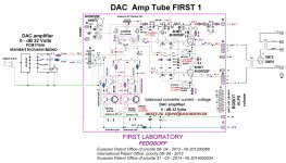
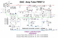
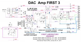
The converter current - voltage linearly operates from 0 Hz - 20 kHz. Modulators PCM1794A loaded on the low output impedance of transistor emiternyh transitions. When the output current 13 mA PCM1794A modulators operate at 2 ohms load resistance. Harmonic distortion at the output of the current conveyor, almost equal distortions PCM1794A. Filtrtsiya high frequency noise of analog filter. The use of batteries can eliminate the noise power and obtain a large dynamic range. Converter - current conveyor is unmatched in sound. This international application is published. See this link: RU2014000255 SINGLE-ENDED AMPLIFIER WITH DIGITAL INPUT, AND DIGITAL-TO-ANALOG CONVERTER AND VOLTAGE FOLLOWER FOR SAID AMPLIFIERThe transformer will by its very nature will alter what comes out. They all seem to sound different. Some prefer a 50% Ni core instead of amorphous iron or 80% nickel.
- Current conveyor creates the shortest path in the world and opens a new era in super high end devices. The output signal of a current conveyor is fed to a powerful single-cycle repeater or a voltage follower. Here is a video where you can hear the sound of the current conveyor battery-powered. ??????????? ???????????? ???????????. ?????2 - YouTube
Attachments
This will need batteries faster than the circuit. Interesting.The converter current - voltage linearly operates from 0 Hz - 20 kHz. Modulators PCM1794A loaded on the low output impedance of transistor emiternyh transitions. When the output current 13 mA PCM1794A modulators operate at 2 ohms load resistance. Harmonic distortion at the output of the current conveyor, almost equal distortions PCM1794A. Filtrtsiya high frequency noise of analog filter. The use of batteries can eliminate the noise power and obtain a large dynamic range. Converter - current conveyor is unmatched in sound. This international application is published. See this link: RU2014000255 SINGLE-ENDED AMPLIFIER WITH DIGITAL INPUT, AND DIGITAL-TO-ANALOG CONVERTER AND VOLTAGE FOLLOWER FOR SAID AMPLIFIER
- Current conveyor creates the shortest path in the world and opens a new era in super high end devices. The output signal of a current conveyor is fed to a powerful single-cycle repeater or a voltage follower. Here is a video where you can hear the sound of the current conveyor battery-powered. ??????????? ???????????? ???????????. ?????2 - YouTube
Look like PCB's I've got some of those. Sorry, they wont scale up full size. When I started hifi I started removing as many components as I could. there are nowa tranch of minimalist DACs that are cheap andbeating DACs at ten times the price (or ) more. This happened with amplifiers and other components. They end up being a penalty giving less than they take from the signal.


regards
666mille
Last edited:
MilleDAC
Hi boldname,
You are right with the minimalistic DAC´s. But this is not the reason I designed this DAC. The main reason is that is a hobby. I don´t want to sell this DAC. So the costs are a minor point. Ok....it´s a little big great (standard Euro-format) 160x100mm.
Here are some headwords:


regards
666mille
Hi boldname,
You are right with the minimalistic DAC´s. But this is not the reason I designed this DAC. The main reason is that is a hobby. I don´t want to sell this DAC. So the costs are a minor point. Ok....it´s a little big great (standard Euro-format) 160x100mm.
Here are some headwords:
- Fully seperated grounds for analog and digital
- 4 layer PCB with gnd and power plane
- 7 power phases (TPS7A3301 and TPS7A4701)
- crystek cchd-575-50-100 ultra low noise crystal oscillator
- Full LME49990 I/V Stage
- LME49600 Audio Buffer for headphone
- Touchscreen lcd
- Amanero Combo384 USB module for 32bit I2s and DSD
regards
666mille
It sure looks a great job, and with the ESS chip and full DSD capability I guess it will do justice to any sound source. Is this your DAC project now done or are you going to keep going on DACS. It would be good to see how this sits against the best commercial. Less than 1ppm? withe reclocking and the selected buffer this should test well with 100KHz square waves.Hi boldname,
You are right with the minimalistic DAC´s. But this is not the reason I designed this DAC. The main reason is that is a hobby. I don´t want to sell this DAC. So the costs are a minor point. Ok....it´s a little big great (standard Euro-format) 160x100mm.
Here are some headwords:
Last but not least the scaled pictures!
- Fully seperated grounds for analog and digital
- 4 layer PCB with gnd and power plane
- 7 power phases (TPS7A3301 and TPS7A4701)
- crystek cchd-575-50-100 ultra low noise crystal oscillator
- Full LME49990 I/V Stage
- LME49600 Audio Buffer for headphone
- Touchscreen lcd
- Amanero Combo384 USB module for 32bit I2s and DSD
regards
666mille
You know, I dont agree with you. There is also no technical justification other than a bit of inductance cleaning the top end. Transformers are useful for doing specific jobs. But we dont find an excuse for using one. True DIYers are really those that make the whole shebang. The dont need these transformers to get darned near the best sound. Lampizator said go direct into the grid of the buffer amp. This in broad terms is correct if you want to use a buffer ampOh, ok. That makes scenes. Using both would not make any sense. These Lundahl transformers are so good that I can't believe people even waste time building analog stages any more. They cost a bit more to buy perhaps but the price is worth it.
Mark
Last edited:
I have Lundahls too. I am having very good luck with Cinemag transformers. They are more affordable then Lundahls. These days I just use transformers for all my filtering. No loss of details... just beware of putting to much voltage across them. In my case less then 1 mV. Enjoy one of the best kept secrets in digital.
Best kept secret for the sound you like.The traffo rolls off the top end and clean up i.e smooth the jitter. The type of sound a traffo makes is not a quality issue but one of impedence match and balancing the FR for a particular type of sound
Lundahls
I have tried many different filter types from Sallen-key to GIC FDNR types. So sure... it is a sound I like. Having said that I prefer Cinamag's at the moment. Passive works well "if" you can tolerate short interconnects 0.5 Meter. If not active would be better. Yes. You must match the transformer impedances or they behave odd. Like most things they have their place however they may not be the best solution in all cases. I see a number of people just using a series coupling capacitor. It works into tube (valve) stuff... I sure wouldn't try that with solid state. BTW: I have a OPPO BDP-83SE with the Saber upgrade. Of all the dac's I own it is #4 in sound quality. Again it is just my preference and yours will be different based on equipment and speakers. I have Magnepan MG 2.5R loudspeakers, very much upgraded and trust me they can rock if you have enough power. However we don't share any common components so at the end of the day "enjoy what you like". 🙂Best kept secret for the sound you like.The traffo rolls off the top end and clean up i.e smooth the jitter. The type of sound a traffo makes is not a quality issue but one of impedence match and balancing the FR for a particular type of sound
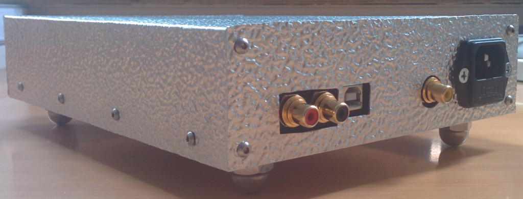
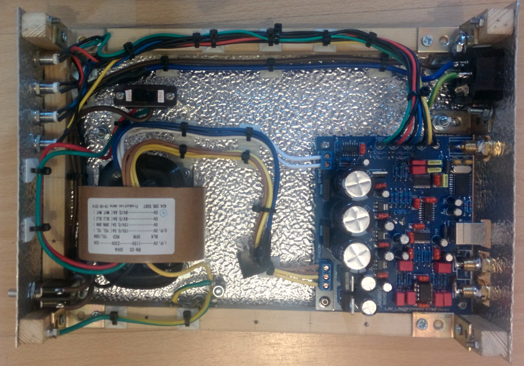
Here is my DAC, based on a CS4398 with CS8416+CM102s kit from ebay ( transformer + empty PCB and components ).
I didn´t build the kit 1:1 but made some changes:
- improved Capacitor values for the power supply ( purchased high quality Capacitors from Panasonic, low ESR )
- purchased 2,5% tolerance Wima FKP2 for the output buffer
- inserted a LME49720 instead of the supplied NE5532
- used better quality RCA connectors ( but since these were not suitable for print layouts, I had to somehow connect them 😀 )
I only used some of the supplied components like eg. the terminals, rectifiers, 1% precision resistors etc. and only upgraded the values on the board where necessary.
In order to make sure that I do the right thing, I also checked the datasheets of the regulators. It´s no use if you try to eg. insert a 10000000000µF cap instead of a 10µF input capacitor for the 3,3V and 5V voltage regulators.
My device has no audible hum and I like the sound. I don´t have the equipment though to perform a advanced analyze of the circuit itself, check the THD etc.
Here are some pictures 😉
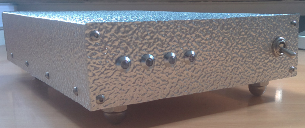
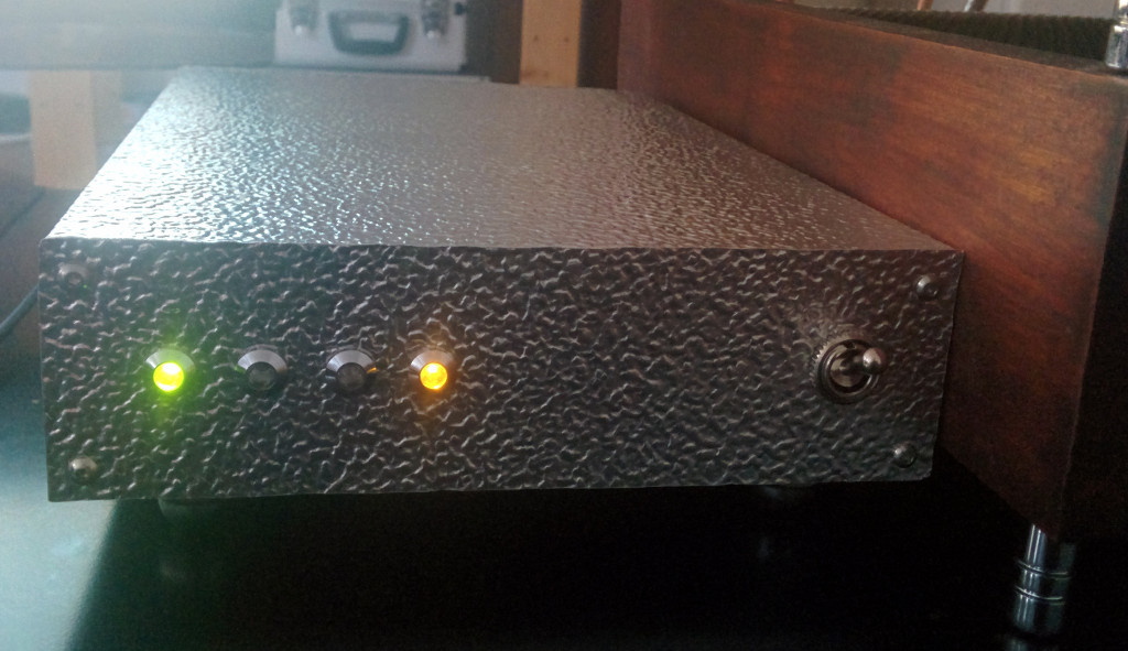
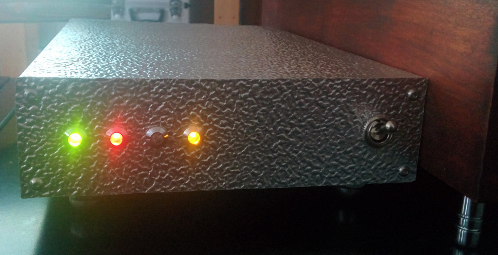
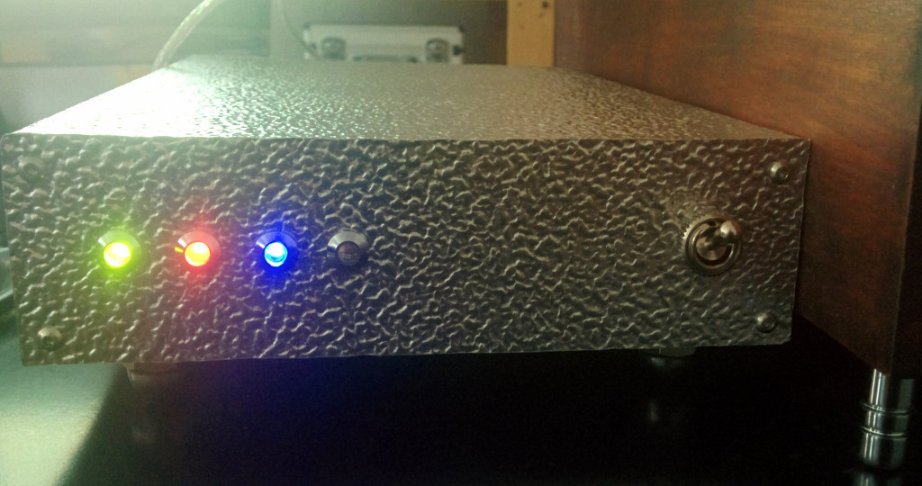
I used a different color scheme for my device instead of 4x blue LEDs:
power: green
signal locked: red
SPDIF: yellow
USB: blue
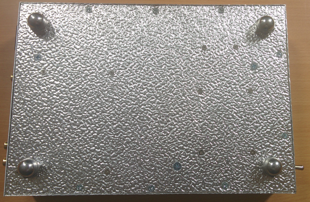
The casing itself is built out of old material I had laying around and even if it´s not perfect, I somehow like the results 😉
Best regards,
I didn´t build the kit 1:1 but made some changes:
- improved Capacitor values for the power supply ( purchased high quality Capacitors from Panasonic, low ESR )
- purchased 2,5% tolerance Wima FKP2 for the output buffer
- inserted a LME49720 instead of the supplied NE5532
- used better quality RCA connectors ( but since these were not suitable for print layouts, I had to somehow connect them 😀 )
I only used some of the supplied components like eg. the terminals, rectifiers, 1% precision resistors etc. and only upgraded the values on the board where necessary.
In order to make sure that I do the right thing, I also checked the datasheets of the regulators. It´s no use if you try to eg. insert a 10000000000µF cap instead of a 10µF input capacitor for the 3,3V and 5V voltage regulators.
My device has no audible hum and I like the sound. I don´t have the equipment though to perform a advanced analyze of the circuit itself, check the THD etc.
Here are some pictures 😉
I used a different color scheme for my device instead of 4x blue LEDs:
power: green
signal locked: red
SPDIF: yellow
USB: blue
The casing itself is built out of old material I had laying around and even if it´s not perfect, I somehow like the results 😉
Best regards,

- Home
- Source & Line
- Digital Line Level
- DAC gallery