Installed LTSpice on the Mac, if someone can help me test the circuit within it that would be fun. To me the effect could be part of slew rate and transient response optimization as well as some EQ/filtering effect, leaving more energy for the rest of the frequencies below the filter slope. If you can do both, then the soundstage would be better.
Yash
Yash
Installed LTSpice... To me the effect could be part of slew rate and transient response optimization as well as some EQ/filtering effect...
Could be internal slew rate of the d-s DAC?
Post-DAC slew rate is not the problem - I feel quite confident in saying that.
But do what you think you should do - and let us know the results.
...leaving more energy for the rest of the frequencies below the filter slope. If you can do both, then the soundstage would be better.
More headroom because of the filter?
Cheers, Joe
I'm traveling now but I will make some measurements when I return. Adding a cap load on a DAC chip will increase its potential for slew limiting. Also tubes can be sensitive to HF and RFI. Its usually not an issue but could be if pushed out of its linear range or at frequencies where a tube could act as a rectifier.
Sent from my MyTouch 4G Slide using Tapatalk
Sent from my MyTouch 4G Slide using Tapatalk
Measuring the effect-
First problem (and this is endemic) is testing with a digitally derived waveform that cannot be recorded from an analog source. Sine waves are legit if in band. Square waves, pulses etc, are marginal at best since they do not represent valid content. Possibly after sample rate conversion (with its internal low pass filter)? While its a good thing to verify performance at the edge of the system failures may not be meaningful.
Next how to test at the band edge and what to test for. 44.1 is pretty easy and I can get really good capture at 192 from a 44.1 source. But- frequency response is not enough. The composite frequency response and phase response is what we want to know. And that must include the ADC. It gets even more complex if the content was recorded at say 96K and resampled to 44.1 for release. The low pass filters in the system are the one in the ADC (one octave higher but still a brick wall, digitally generated) the one in the down sampling algorithm and the one in the DAC.
If you have played at all with cascading filters you would understand that there will be consequences to piling on filters, usually not good ones.
I can measure analog frequency response with good resolution to probably 1 GHz and SOTA to about 5 MHz. I can also measure phase to 13 MHz. But the delay through the AD-DA chain will make that really difficult if even possible. Below 90 KHz I can use Praxis for analog/digital and hybrid measurements and because its a speaker program I can dial in delay to account for the delay through the chain. (It even works for Bluetooth!) But it doesn't work for mixed sample rates. I'll try a few measurements when I get back next weekend and see what I see.
Maybe the low pass filter needs to be different for different sources? Maybe (brain twister here) it needs to be an all pass network to correct for phase buildup and the low pass filter is only a start?
This problem actually get more complex the more you look at it.
I don't have any sound cards and not well versed in them - but I do see increasingly less expensive equipment available, can anybody make some comments about what is available - and cost, pros and cons. I think that could be shared and would be appreciated by others.
The nice thing is that all you need is a good ADC (a good studio ADC for audio work, an USB oscilloscope front-end for higher frequency stuff), and all the rest can be done using (free) software.
I find audacity and especially SoX great tools for generating test signals in digital form. And both are free...BTW, the Clio have heaps of stimuli it can generate - but not that easy to insert into a digital stream as its output is analog - unless burnt to disk I suppose from files - but I should be able to generate many different frequencies and even combination of frequencies, but burning to disk I would have to rely on a soundcard and ADC - better if somebody had files that they could make available here or post them on a server - or I could even store it on my website and supply URL to download them.
What is causing the jitter?jitter is a huge problem in dynamic speaker systems
Hi Joe.
Well, I see you have big plans to work with...😉🙂
Of course one may have his own skills and capabilities, but any kind of contribution it may be fortunate and it may push things forward in finding more about this filtering way. I think we may concentrate us mainly now in how to come with some facts about what we hear (those who have heard it so far...). And then analyse it more and go "theoretically". But yes, this is enough clear, this filtering technique is to be used with big success.
From my part I have got an idea and I`m working with it now. I will come soon with some details about some measurements.
I find audacity and especially SoX great tools for generating test signals in digital form. And both are free...
You mean you can generate clean sine waves without resorting to my Clio and then converting? Now that I would like to see.
What is causing the jitter?
It comes down to the fact that it is not voltage across the Voice Coil that makes it move (it is a motor), but rather the current through the Voice Coil. Note that juxtaposition of across and through. So voltage across a Voice Coil should be a function of current through VC. Yet it is not (for a start, current send will always have a zero degree current phase angle - and in reality it is not, since they are voltage sources that can produce any phase angle). There are two points to be made, one is that ideally we should use current to drive VC and not voltage and also, when we model multi-driver speaker systems and their Crossover, they are modeled according to voltage. But that is just part of it and this being OT I don't feel I should explain in detail. Your countryman Esa Merilainen has written a contentious book on "Current Driving Loudspeakers" (see Current-Drive - The Natural Way of Loudspeaker Operation that has gotten a lot of people off-side and it makes this issue of a filter on d-s DACs a minor skirmish in comparison. Esa and I have of course had our exchanges and I am largely supporting him - but we have a different approach to finding acceptable solutions. Mainly because, there are signs of a real break-through down here. But suffice to say, that when current and voltage is not in sync and with reactive Crossover components, the result is large amounts of phase noise, ergo jitter. But I have to say that some of the guys down here don't want to call it jitter or noise (as it is not random), yet Dave Wilson of Wilson Loudspeakers is openly calling it jitter and claims his Crossovers are "anti-jitter" - so that has stuck.
As I said, this barely touches at it -and it is OT. No, this is not yet the time to open a thread about it, but sometime in the future I suspect we will see a lot of discussion on this. It is the leading edge right now and there is much more to come. Wilson is keeping very quiet, but we know his technique and the technique we are developing is far more sophisticated and has broader applications.
The Linear Current Loudspeaker - This was as yet early thinking and we have come a long way since, but still interesting.
Cheers, Joe
.
You mean you can generate clean sine waves without resorting to my Clio and then converting? Now that I would like to see.
And why wouldn't you be able to generate them? Absolutely no problem:
Code:
sox -n tone.flac synth 10 sin 440There are two points to be made, one is that ideally we should use current to drive VC and not voltage and also, when we model multi-driver speaker systems and their Crossover, they are modeled according to voltage.
Yes, current drive seems to be one of the latest fads, but I would call the effect you describe simply "phase error" (something you get even from the inductance of the voice coil), and not "jitter".
Yes, current drive seems to be one of the latest fads, but I would call the effect you describe simply "phase error" (something you get even from the inductance of the voice coil), and not "jitter".
I am inclined to agree with you re fad (and phase error too) - it is not going to take off. Re current drive, it is not practical and this is where Esa and I see it differently - he wants us to use current drive and that is ultimately of no commercial value. We aim to achieve pseudo-current drive from a voltage source and make the speaker compatible with any source Z, where current drive is high Z and voltage is low Z. That is where the real pay-off lies, in more sense than one. I have a current amp with an output Z of 270 Ohm - need I point out what a dangerous device that is? That is why you won't see any in any shop. As I said, this is only the tip of the iceberg and there is some serious maths to be worked out - and it is OT on this thread.
Back on Topic: Yes, I want to generate some suitable files and do some measurements - and hope that others will too.
And bear with me on this one, right now I have a huge workload - but I do want to attempt those measurements with my Clio soon. If I need help, do you mind if I holler - I don't mind the guidance on this. Not everything has to be about showing off one's ego. You can't be an expert on everything and if I need expertise I don't have, I seek it.
Cheers, Joe
.
Last edited:
I have a current amp with an output Z of 270 Ohm - need I point out what a dangerous device that is?
Not any more dangerous than a high-powered valve radio transmitter. 🙂
No, I wouldn't want to have either unprotected in my living room....
Joe and Jult if you can bring up some good test setup in that manner, i guess it maybe could be dublicated to us hobbyist/diy'ers lesser budget in form of example Arta or REW combined with available desktop/labtop/soundcards...........measurements with my Clio soon..........
Joe the work on speakers filling your life at present is very exiting, took a look at your link The Linear Current Loudspeaker. Many these days in digital domain fights making linear phase for drivers so to reproduce better step response and even square waves. All this is complicated but can be done, but at the cost of delay for compute time. This delay compute time can be brought down to non problem for home setups, but a problem for live and studio setups.
Your setup ideas also looks to get linear phase, therefor i ask can that setup also produce nearly perfect step response and square waves but in realtime, or do it also introduce some delay.
Sidenote, if you get the speakerproject at track, then apply same principles to microphones and we get better recording and reproduction 😉.
Well, well... We have some tests...
Not quite well results...🙁 But results at least to start with. There is not less "smog" after these tests, I may say...
First let`s take a look at what I`ve done so far.
I have used a brand new and unmodified Xonar STX sound card (For sure, I did not bought it for this test 😀 )
Computer running win 8/64bit, Quad cores i7 processor, lot of memory, and so on...
Loop from Line output to input. Used RMAA Pro audio analyses software.
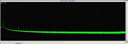
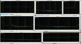
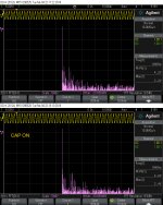
I have tested first the sound card as it is, and you may see here the results. You may note that the channels on this board are not quite equal. Asus made in China quality...😉 Then I have soldered in the caps over the DAC (PCM 1792) output phases, and tested again in the same setup. You have also the pictures here (pictures marked with "CAP ON"). Of course I have also listened to a test recording (that I have used earlier for my illustration of the sound stage changes), played out on this unmodified board. I used 1n film SMD cap, as you can see in picture. The same cap I use on my modified board and it gave me an obvious effect. It may not be the best choice, for the best effect, but for test purposes, I appreciated as good enough.
You may also note that the board have already all the filtering in place, as the factory designed and deliver it.
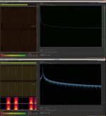
I did another test using a 1Khz sine generated file played out with Foobar/ASIO64bit Out on the sound card, and recorded in with Adobe Audition/MME/LineIn input. The same computer, the same sound card with loop connection on it. Without cap on board, and with cap on it. You have the results on the picture here by.
One may note here that are to be seen some artefacts or breaks in streaming of this file in the system. Is due for sure to the way the playback and recording are made using the same hardware. There may be not enough time for both tasks somewhere in processing... This issue it happen also in both cases (with/without caps), so has not a so big impact for the final conclusion of the tests.
The most exciting for me was to find out if on this brand new sound card, which is a good enough consumer device, the effect of these caps it might be the same obvious as I experienced on my modified board (same type).
At once, the caps it were in place, the sound scene it were open, the bass got deeper and weighty. Well, all the good and benefits of this effect it were present. So I test it with RMAA...😕
Up to you to judge this further contradictory approach. While the test shows not so good, the ears and brain says WOW!
Not quite well results...🙁 But results at least to start with. There is not less "smog" after these tests, I may say...
First let`s take a look at what I`ve done so far.
I have used a brand new and unmodified Xonar STX sound card (For sure, I did not bought it for this test 😀 )
Computer running win 8/64bit, Quad cores i7 processor, lot of memory, and so on...
Loop from Line output to input. Used RMAA Pro audio analyses software.
I have tested first the sound card as it is, and you may see here the results. You may note that the channels on this board are not quite equal. Asus made in China quality...😉 Then I have soldered in the caps over the DAC (PCM 1792) output phases, and tested again in the same setup. You have also the pictures here (pictures marked with "CAP ON"). Of course I have also listened to a test recording (that I have used earlier for my illustration of the sound stage changes), played out on this unmodified board. I used 1n film SMD cap, as you can see in picture. The same cap I use on my modified board and it gave me an obvious effect. It may not be the best choice, for the best effect, but for test purposes, I appreciated as good enough.
You may also note that the board have already all the filtering in place, as the factory designed and deliver it.
I did another test using a 1Khz sine generated file played out with Foobar/ASIO64bit Out on the sound card, and recorded in with Adobe Audition/MME/LineIn input. The same computer, the same sound card with loop connection on it. Without cap on board, and with cap on it. You have the results on the picture here by.
One may note here that are to be seen some artefacts or breaks in streaming of this file in the system. Is due for sure to the way the playback and recording are made using the same hardware. There may be not enough time for both tasks somewhere in processing... This issue it happen also in both cases (with/without caps), so has not a so big impact for the final conclusion of the tests.
The most exciting for me was to find out if on this brand new sound card, which is a good enough consumer device, the effect of these caps it might be the same obvious as I experienced on my modified board (same type).
At once, the caps it were in place, the sound scene it were open, the bass got deeper and weighty. Well, all the good and benefits of this effect it were present. So I test it with RMAA...😕
Up to you to judge this further contradictory approach. While the test shows not so good, the ears and brain says WOW!
Attachments
-
 TestSoundcard.jpg606.7 KB · Views: 239
 -
 PlayFoobarASIO1khz-RECAuditionMMErecLOOPstx.jpg388.6 KB · Views: 148
 -
 TESTResults.jpg339.1 KB · Views: 131
 -
 THDcapON.jpg426 KB · Views: 118
 -
 NoiseLevelCAPon.jpg564.2 KB · Views: 126
 -
 InterMODcapON.jpg572 KB · Views: 216
 -
 Freq&THDcapON.jpg590.9 KB · Views: 221
 -
 DynRcapON.jpg548 KB · Views: 221
 -
 Kernel-MMElineINloop32bit-192Khz-OrigSTX.jpg783.4 KB · Views: 234
 -
 IMDcapON.jpg457.4 KB · Views: 118
Last edited:
If you don't have the resistors after the cap there is a good chance the opamp will be unstable. I'm not able to open the pictures on my phone so I can't see what you did.
Sent from my MyTouch 4G Slide using Tapatalk
Sent from my MyTouch 4G Slide using Tapatalk
Hi
Just came across this thread.
A few years ago I was working on a Pioneer 565 universal player that used a DSD1971
voltage DAC. I used a 1:2 step up transformer across the differential o/ps without any following op amp filter, This sounded very nice to me but my colleague felt it still sounded a little "digital" (If I can call it that) on CD in comparison to DVD and DSD.
Anyway I found that the transformer was loading down the DAC o/p at very low frequencies and to cure it I added some series resistance in the leads to the transformer. This worked but caused a slight dip in the frequency response of around -1db at 20Khz. Unexpectedly this also fixed the apparent CD problem to the delight of
my colleague. I do remember at the time that -1db was about the right figure
any more and the sound got worse. I didnt finesse it to -1.3db though.
So what Im saying is I think I had exactly the same experience but arrived at in a different way.
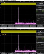
tons of IMD!!!... That crap is added to signal....maybe is nice sounding crap 😀
It's My-Fi, not Hi-Fi.
It's My-Fi, not Hi-Fi.
Hi
Just came across this thread.
A few years ago I was working on a Pioneer 565 universal player that used a DSD1971
voltage DAC. I used a 1:2 step up transformer across the differential o/ps without any following op amp filter, This sounded very nice to me but my colleague felt it still sounded a little "digital" (If I can call it that) on CD in comparison to DVD and DSD.
Anyway I found that the transformer was loading down the DAC o/p at very low frequencies and to cure it I added some series resistance in the leads to the transformer. This worked but caused a slight dip in the frequency response of around -1db at 20Khz. Unexpectedly this also fixed the apparent CD problem to the delight of
my colleague. I do remember at the time that -1db was about the right figure
any more and the sound got worse. I didnt finesse it to -1.3db though.
So what Im saying is I think I had exactly the same experience but arrived at in a different way.
Indeed, this it looks very similar to what we talk about here...
If you don't have the resistors after the cap there is a good chance the opamp will be unstable. I'm not able to open the pictures on my phone so I can't see what you did.
Sent from my MyTouch 4G Slide using Tapatalk
I have tested with resistors in a different test session, and I`ve got only a worse sound on output. It were better sound when I had only the caps in this test configuration I used. But in the same time is this IMD which is really bead...
I see very well the paradox here: it looks bad on tests, but it sound well. Is really hard for myself to accept this.
I think it will help if many will want to experiment with this, and will try to find out more about what is going on here.
Until I will repeat and improve the tests on this, maybe somebody else will come with some more informations, results, etc.
I see very well the paradox here: it looks bad on tests, but it sound well. Is really hard for myself to accept this.
Why? It is well-known that people tend to prefer certain forms of distortion.
More headroom because of the filter?
Cheers, Joe
Could be to some extent: when mixing and mastering, it is best practice to minus EQ'ing rather than boost deficient frequencies, i.e. if a mix is lacking in high frequencies, one would have a tendency to boost the high-frequency with the EQ circuit or plugin, but with experience, the best mixing and mastering engineers know that it's better to diminish low-frequency content instead as they dominate a lot of the sound energy.
Transient response would have a greater effect in my opinion.
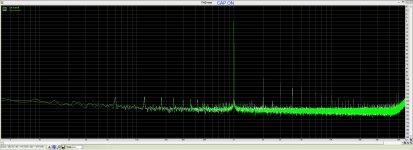
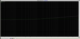
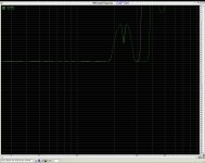
A little bit more testing...
This time without loop connection. A 1Khz and 20Khz sine signals files played out on the sound card, with/without caps connected. Signals are measured on output RCAs of the board.
I have verified the "rule" for setup of the filter: there is -1.2dB on 20Khz relative to 1Khz, using 1nF on this hardware.
Attachments
- Status
- Not open for further replies.
- Home
- Member Areas
- The Lounge
- DAC Filtering - the "Rasmussen Effect"