Thanks for the hex file, but I meant the actual source code. Are you also willing to share that too?
Hi Corpius!
I am so sorry you are.
expect sympathy.
I would like to thank you
quanghao
Dear Corpius and Quanghao!
From logical standpoint problem should be located in hardware and not in firmware.
Everybody has the same firmware but only me and Corpius experience such kind of problem.
Yesterday I sent my module back to Quanghao to locate the problem and repair or exchange because my dac totally refused to lock to usb and optical and issued hissing sounds during startup.
Daniil
It's OK if you don't want to share the source code.Hi Corpius!
I am so sorry you are.
expect sympathy.
I would like to thank you
quanghao
danielkol, I'm not sure about that.Dear Corpius and Quanghao!
From logical standpoint problem should be located in hardware and not in firmware.
Everybody has the same firmware but only me and Corpius experience such kind of problem.
Yesterday I sent my module back to Quanghao to locate the problem and repair or exchange because my dac totally refused to lock to usb and optical and issued hissing sounds during startup.
Daniil
It happened again today and I restarted the computer, but it did not help. The DAC stays in some strange lock state.you usr jiver media ??
if us it, it is very very always wrong when play music,
so need re stat your computer, and play again!
thanks
When the problem occurs the dac chip can't be controlled somehow. The controller still does respond to the remote, but the actual volume is not changing and I can't switch inputs anymore. My computer says that the Amanero is working correct and the DAC is still playing music, but I can't control it when this happens. That's why I think that it might be controller or firmware related. It could also be that the ES9018 chip isn't working as it's supposed to do. I can check that by using my own controller. If the problem only occurs with the original controller then it must be the controller or firmware related.
Hi all,
this morning i had a similar problem.
I heard my breakfast music over USB input and suddenly after a few minutes the display row with the no lock info began to blink fast and the sound was very distorted.
The difference to my setup yesterday: I moved my components in the hifi rack to get the CD-player plugged in to. I thought it must have to do something with the newly plugged in CD-player on the coax input which was not powered on today because i heard from pc.
I unplugged the coax and the blinking disappeared. But the sound was distorted anyway.
Then i powered off and repowered the DAC after a while. Now with coax input not plugged in the usb was ok and played fine.
I think this has to do with plugged in components while they are not powered on or terminated correctly. As posted before it is a similar behavior with a plugged in XLR-cable which ends open.
jogi
Hi Corpius,
DAC, CD-player and amp are earthed over the mains plug earth. But not directly the chassis because it's not a good idea to do it multible ways.
jogi
DAC, CD-player and amp are earthed over the mains plug earth. But not directly the chassis because it's not a good idea to do it multible ways.
jogi
After Anjogi posted that he got problems after plugging in his CD-player at the SPDIF input I started to think about grounding problems. So I moved the DAC to another room, which has no earthed wall sockets. My DAC plays without error when the audio equipment is not earthed.
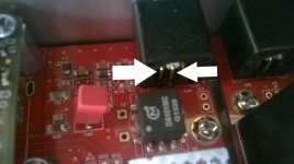
After that I started measuring for continuity at some places that need to be isolated from each other. I found that the gnd at the SPDIF connector makes direct contact to the gnd of the DAC, despite the digital transformer. Also the spdif signal at the connector makes direct contact to gnd!
I added a picture with white arrows that point to the leads of the spdif connector. These make contact with each other. My multimeter measure 0 ohm resistance. Nevertheless the DAC plays fine with only SPDIF.
Quanghao, Andrea: It looks like a design error or perhaps a mistake was made during soldering. Can you elaborate on this?
Perhaps somebody would like to measure these points for continuity? I'd like to know if this is the actual design or a mistake a my DAC.
Attachments
Please understand my right:
The problem is not playing spdif over coax input. That plays wonderful. The problem was when CD over spdif plugged in, CDplayer is off and i play with USB input.
I didn't yet check whether the problem is also there if CDplayer is on.
I think it's ok that spdif has ground. How should it play without? The problems for groundloops are multiple grounds. Therfore the DAC should only be grounded at one point. That's the ground of mains plug.
I do not think that there is a ground problem.
jogi
Last edited:
I did understand that you have no problem with playing via coax. But the spdif ground should be isolated by the transformer, just like the signal. That's the whole point of using a transformer at the input.Please understand my right:
The problem is not playing spdif over coax input. That plays wonderful. The problem was when CD over spdif plugged in, CDplayer is off and i play with USB input.
I didn't yet check whether the problem is also there if CDplayer is on.
I think it's ok that spdif has ground. How should it play without? The problems for groundloops are multiple grounds. Therfore the DAC should only be grounded at one point. That's the ground of mains plug.
I do not think that there is a ground problem.
jogi
Some more measurements:
I just measured at the same points of my Rega DAC. Measuring 0 ohm between signal and ground seems to be normal when there is a transformer involved, but my Rega DAC has has no continuity between spdif ground (at the connector) and DAC ground. It's isolated by the transformer, just as I thought it would be.
Hi Steve
How are you finding the DAC - any impressions you could share maybe compared to other DAC's you have owned?
Thanks
How are you finding the DAC - any impressions you could share maybe compared to other DAC's you have owned?
Thanks
Quanghao,
Just wanted to give a quick update that I received my DAC! It looks beautiful!!!! 🙂
I haven't yet had a chance to test it out, but I'm sure it will be fine.
THANK YOU for all of your hard work on this project.
Kind regards,
Steve
problem solved
I was able to pin down the problem I was having with my DAC. I must have been plagued by ground loops. The problem always occurred when I connected the DAC to a earthed wall socket. There is no problem when the wall socket is not earthed. The computer I use for playing media is also earthed so that's probably how the ground loop could be completed.
I solved the problem by replacing the metal spacers by plastic spacers. That way the circuit ground becomes fully isolated from the chassis and the chassis can stay earthed. For safety reasons obviously.
I still need to take a look at why the ground at the spdif connector connects to the circuit ground... despite of the pulse transformer.
I found your problem, and it seems it would be the case for every kit. Good finding by the way! I measured my own DAC and I found the same problem as you, the coax input connector gnd is indeed connected to the Dac ground defeating the purpose of an insulation digital transformer at the input.
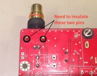
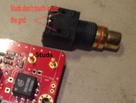
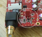
The cause is simple and it is an error in the PCB design. Look at the included picture. In this type of RCA connector, the two large connector mounting studs (circled in black on the image) are connected to the rca gnd. The correct PCB would have these two studs insulated from the PCB gnd.
To correct this is a little tricky for the some of you guys. The pcb been to faces, these two pins are grounded on both top and bottm sides, meaning that we cannot just cut the pcb around the stud on the bottom face to cure the problem. First you need to unsoldered the connector (that is the tricky part) without damaging the board, cut the pcb ground around each mounting stud, double check with an ohmeter the insulation, the re-solder the connector. That will correct the problem.
WARNING: If you're not sure of your soldering skills and/or don't have the proper tools, you can damage the PCB...
I'm doing it right now.
Attachments
False alarm, I removed the connector, and the two studs came out of the connector casing. I can see that inside the plastic the studs are not touching, so they are insulated. Looking closely at the under of the PCB, there is the answer. A piece of wire was added between two pads, one being the PCB gnd. This jumper ground the coax ground. We need to remove this jumper. Confirming right now...
Attachments
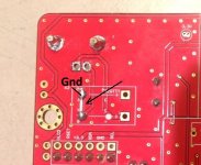
I can confirm that removing the jumper cure the problem. Simple as that. The input transformer is correctly installed on the PCB, and it doesn't seem to be any error of the pcb. I don't know why this jumper was installed 🙄
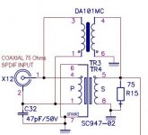
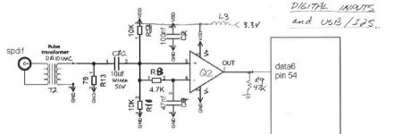
In some coax input implementation there is a small cap (47pf here) between the primary ground side of the connector, see schematic. This is something we may try as well. Just install the cap in place of the jumper.
In some coax input implementation there is a small cap (47pf here) between the primary ground side of the connector, see schematic. This is something we may try as well. Just install the cap in place of the jumper.
Attachments
Last edited:
I haven't found the time yet to look at why the connector ground connects to the DAC ground, so you beat me to it! Good work!
I also noticed the jumper wire underneath the PCB in this post from quanghao. My first impression was that it was needed to overcome some difficulty in PCB design, but perhaps it was there for testing purposes and quanghao forgot to remove the jumper before shipping the DACs. Who knows?
Can you confirm that the coax input still works with the jumper removed?
Now about the coax input implementation. There already seems to be some circuit in use at the connector ground side that implements a cap and some resistors. I not at home right now, so I can't check the exact circuit.
Attachments
Yes it is working right now. Check the input schematic included, all the circuitry is on the secondary side, not the primary. This Wima red cap is the 10uF input cap on the schematic. I reversed engineer all the dac schematics by the way 😉
Very nice design all around.
Very nice design all around.
Attachments
Last edited:
Right, so it's not on the primary side.Yes it is working right now. Check the input schematic included, all the circuitry is on the secondary side, not the primary. This Wima red cap is the 10uF input cap on the schematic. I reversed engineer all the dac schematics by the way 😉
Very nice design all around.
Wow you've reverse engineered all the schematics! You sure have put a lot of effort into it! Are you willing to share those schematics?
Not really, first they are not mine to disclosed, Quanghao has the intellectual rights, second there is no warranty my schematics are without errors, there are grey zones for some smd parts for example, etc. I don't want to hear about what I may I figure out wrong, or argue on my own choice of parts and/or values. You have the PCB to look at it. It is all in plain site. You'll have a chance to appreciate the PCB routing, supplies decoupling and grounding. When you know what to look for you can appreciate the design quality. The next best thing would be to have a 4-6 multilayers PCB, but the cost of it is probably prohibitive for the DIY market. Not mentioning that to work on such PCB is a nightmare if you want to repair, change/upgrade it.
Just to let you know that with the already disclosed information (look at Dac version 1 and the AD1864 DAC threads as well), and Quanghao block diagrams you should have a petty good idea of what is going on. For example the complete digital input section is about the same as the one already shown for version 1. There is just a few better/different LC supplies filtering added, and parts re-numbering, the basic concept is the same. Same thing for the clock buffer and Amanero insulator. Look also at part datasheets, it was very informative.
It took me just a few hours to get the complete DAC circuits, and about one day for the different IV pcb sections. Feel free to do the same. It was fun 😀
Last edited:
perhaps I'll do that one day, but I'm too busy with other things at the moment. I guess that it's all a matter of priorities 🙂 I do fully understand why you are not willing to share. No hard feelings from my side.
the design quality is indeed outstanding. I enjoyed this dac since the moment it arrived at my home. Nevertheless some problems need to be solved to make it even better. That's DIY!
the design quality is indeed outstanding. I enjoyed this dac since the moment it arrived at my home. Nevertheless some problems need to be solved to make it even better. That's DIY!
Indeed. Main reason I did it was to be able to support it in the future and how I can adapt some of it in my own projects.
- Status
- Not open for further replies.
- Home
- More Vendors...
- Quanghao Audio Design
- DAC-END R (ES9018) full assembled board - version 2