Abraxalito's member I/V based on a strong low pass filter passive before the I/V. It is a kit.
It is a DAC output stage comprised of a low noise discrete opamp stage to convert the DAC current out to voltage out and a analog reconstruction filter in one board.
Noob question. Is the opamp working in classA in the original configuration?( No mods to the board)
Depends on the opamp. Discrete ones (most popular ones) run in class A. Ic ones AB. They can run in class A, but it's not done in the original configuration of the boards. You can purchase adapters that push ic opamps to run in class A.
Is standard configuration with the components of the BOM.
Opamp is LM6171.
How can it be configured to work in classA.
Is the power supply sufficient?
Opamp is LM6171.
How can it be configured to work in classA.
Is the power supply sufficient?
It is just an example of an opamp, you can use most, but do care, some older ones need compensation.
Yes, supply is more than enough. Imma be honest, get a discrete opamp if you want it in class a. Risking ic opamp going into thermal runaway (with just adding css), not a good thing. In your case i'd plop opa1656 into and enjoy music.
For me, proper way to put ic opamp in class a is to bootstrap it, and i'm not sure there is an adapter for that online.
From what I read so far, the output of the opamp need to be connected to the V- powerrail by a resistor, some CRD or some small Jfet network.
For a 2V output, biasing into classA would be sufficient with just 4mA output. No need to bias it higher to avoid thermal problems.
Then again I'm new to this.
If it's not over complicated why it isn't used more? 🤔
What's the benefit? Lower distortion. No crossover distortion? ...
https://tangentsoft.com/audio/opamp-bias.html
If you connect resistor, it won't prove to be a sufficiently good current source, as when you play music your opamp output is not zero, so current will deviate. Jfet network you speak of is constant current source, it keeps the current stable.
It isn't used more because opamp is a quick solution, and this complicates things, without much benefit as opamps already carry very very low distorsion. And AB (most if not all modern opamps are class AB) doesn't have significant/audible crossover distorsion, like old class B opamps would have. Also class AB doesn't carry significant harmonics from power supply into signal, like class B does.
If you want class A, i still suggest using discrete opamp designed for it, or use discrete output stage instead of an opamp.

I tried that a long time ago with a resistor to push it to A class. I didn't notice any significant difference. But let everyone try it for themselves. It's pretty simple. CCS is better option.
Happy to reply to this thread on DIYaudio.
I built a NOS AD1862 according to the circuit diagram in this thread.
But somehow, when I connect it to an amplifier, I can hear obvious "digital noise" at low volume.
It is very quiet when there is no I2S signal input 。。。
Has anyone encountered the same problem as me?


I built a NOS AD1862 according to the circuit diagram in this thread.
But somehow, when I connect it to an amplifier, I can hear obvious "digital noise" at low volume.
It is very quiet when there is no I2S signal input 。。。
Has anyone encountered the same problem as me?
I didn't hear any noise with the Miro boards. There is noise and harmonics on the oscilloscope certainly because it is a NOS DAC without a filter, the output is a stepped sine when there is a signal but it is not in the audible range. I can see it all, but I can't hear it.
You can post images of your layers/layout. And rest of the circuit diagram. One thing i notice right off the bat is that your c7 and c18 need to be 1uf instead of 10uf, since your c8 and c17 are 10uf. They are to keep ration of 1:10. And they are noise reduction capacitors, could explain what you're hearing.
Is there a way to determine how far in class a an opamp is tuned?If you connect resistor, it won't prove to be a sufficiently good current source, as when you play music your opamp output is not zero, so current will deviate. Jfet network you speak of is constant current source, it keeps the current stable.
It isn't used more because opamp is a quick solution, and this complicates things, without much benefit as opamps already carry very very low distorsion. And AB (most if not all modern opamps are class AB) doesn't have significant/audible crossover distorsion, like old class B opamps would have. Also class AB doesn't carry significant harmonics from power supply into signal, like class B does.
If you want class A, i still suggest using discrete opamp designed for it, or use discrete output stage instead of an opamp.
I understand your suggestions of a discrete opamp.
I see it more as an experiment from the "standard configuration". So don't want to deviate to much from it to keep it simple.
Thanks for the reply. But I don't think it's C8 and C17 that cause this "digital noise"You can post images of your layers/layout. And rest of the circuit diagram. One thing i notice right off the bat is that your c7 and c18 need to be 1uf instead of 10uf, since your c8 and c17 are 10uf. They are to keep ration of 1:10. And they are noise reduction capacitors, could explain what you're hearing.
I also tried changing them to 1uF capacitors. This "digital noise" still exists
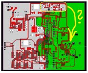
Here is my PCBLAYOUT, thanks!
I use xmos to convert USB audio to I2S signal, connect this AD1862NOS test board, and connect it to my desktop speakers through the amplifier.
This "digital noise" does not always exist. When I play audio on the computer, it will appear at the same time as the music, and it is particularly obvious when the volume is low.
When the music player software is closed, this sound will also disappear.
This "digital noise" does not always exist. When I play audio on the computer, it will appear at the same time as the music, and it is particularly obvious when the volume is low.
When the music player software is closed, this sound will also disappear.
@CNOracle Where did you connect AGND together with GND? You should connect it together under DAC chip. If it is not connected, bridge DAC pin 9 with pin 12 using a thicker wire (under both DAC chips) 🙂
Also remove trimmers from DAC chips because without a proper equipment you can not adjust bits better than factory 😉
Also remove trimmers from DAC chips because without a proper equipment you can not adjust bits better than factory 😉
Thanks for your reply.@CNOracle Where did you connect AGND together with GND? You should connect it together under DAC chip. If it is not connected, bridge DAC pin 9 with pin 12 using a thicker wire (under both DAC chips) 🙂
Also remove trimmers from DAC chips because without a proper equipment you can not adjust bits better than factory 😉
I connected GND and AGND together at the red arrow position through a 0Ω resistor.
If this "digital noise" is caused by GND problems, it should always exist, but in my case, it only appears when there is music.
I will try the grounding solution you suggested.
- Home
- Source & Line
- Digital Line Level
- DAC AD1862: Almost THT, I2S input, NOS, R-2R