@passive420 what is feeding the ian canada's I2S to PCM board?
And what is your plan for the IV since you have wanted it to be off board from the DAC section?
And what is your plan for the IV since you have wanted it to be off board from the DAC section?

PSU2 Mini (Minus)
PCB size: 75x25mm
Mouser example -12V:
https://eu.mouser.com/ProjectManager/ProjectDetail.aspx?AccessID=0a78613ee8
200k trimmer from aliexpress: https://aliexpress.com/item/1005001844551366.html
(untested)
wow, very cool 🙂 . Thank you. Can you say more about that smd reg ic ?
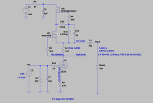
Not sure C3 is needed due to the tinny distance between C2 and the reg input. Instead I will save the space to make a serie resistor between C1 and C2 : thick film, MELF or THT if flipped at 90°
They don't have an exact specification yet, but it can save costs and space in the resulting DAC 😊for what are all these little beauties? Don't tell me pcm reclock.... So we need an ad1865 SMD but with usual connectors now 😱
Regarding C3 I basically followed the previous design where I studied this capacitor and found it useful, but now completely forgot the subject 😀 Something seems to me that it somehow improves stability, but not significantly ...wow, very cool 🙂 . Thank you. Can you say more about that smd reg ic ?
Not sure C3 is needed due to the tinny distance between C2 and the reg input. Instead I will save the space to make a serie resistor between C1 and C2 : thick film, MELF or THT if flipped at 90°
I was thinking about this resistor, but in the end I did it without, anyway inductor could be a better choice 🤔
but in this way I can build all the DACs I want, with these MINIMINI boardsThey don't have an exact specification yet, but it can save costs and space in the resulting DAC 😊
 😍😍😍😍
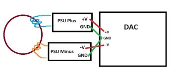
😍😍😍😍@miro1360 & @Michelag - when using the separate rail PSUs above with one of Miro's DACs, will each rail have a seperate Gnd? For a three pin connector on the DAC board, which GND would you use?
Connecting the GND terminals together would cause a loop?
I only ask as I tried to build a dual polarity supply with separate boards and connecting the 0V caused a hum. Same transformer with dual secondaries.
Connecting the GND terminals together would cause a loop?
I only ask as I tried to build a dual polarity supply with separate boards and connecting the 0V caused a hum. Same transformer with dual secondaries.
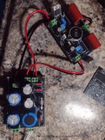
I need some help figuring out this tube setup Michelag. I have 237v dc going into the tube pcb, I have 237v at the center pin on the 2 transistors but then at the plate pin I have the voltage slowly creeping down from 237 and now it has dropped to 40v at the plate pin and still dropping. I havent installed the tube, but what voltage should I be getting at the plate pin or the outside legs of the two transistors? I attached some pics of my current setup
Attachments

@Michelag You are good to go without inductor 🤣 But the door is open for testing, track between capacitors is long enough to scratch and place and inductor between 
@passive420 Exactly like Michelag said, both power supplies are connected together on DAC PCB. ... Maybe your question was about whether they can be connected together to form a symmetric power supply? They can be connected together with GND terminals 😉
@passive420 Exactly like Michelag said, both power supplies are connected together on DAC PCB. ... Maybe your question was about whether they can be connected together to form a symmetric power supply? They can be connected together with GND terminals 😉
Attachments
Install the tube before than immediately 😁(triple check the contacts on the socket), and regulate potentiometer to get 100V on the plates on both sides.I need some help figuring out this tube setup Michelag. I have 237v dc going into the tube pcb, I have 237v at the center pin on the 2 transistors but then at the plate pin I have the voltage slowly creeping down from 237 and now it has dropped to 40v at the plate pin and still dropping. I havent installed the tube, but what voltage should I be getting at the plate pin or the outside legs of the two transistors? I attached some pics of my current setup
To avoid loops, connect the ground of B+ only on one side, they're connected on the psu board.
Measure in the B+ what pin is positive, I didn't write that explicitly on board, if I recall right
Inductor, yup, but the size???? That's strange C3 serves because the very narrow distance ?! Dunno !Regarding C3 I basically followed the previous design where I studied this capacitor and found it useful, but now completely forgot the subject 😀 Something seems to me that it somehow improves stability, but not significantly ...
I was thinking about this resistor, but in the end I did it without, anyway inductor could be a better choice 🤔
Between C2 and C3 the reg should be lloaded from C2 before C3 because of ESR, no ? Anyway this is why I could do this cut with a resistor (or an inductor) for the reg does see the smoothing post rectifier current imo but only from C2 if the resistor before. Here C2 became a reservoir cap w/o that flip fop due to rectification, you can twice C2 capacitance if you want.
pretty sure my polarity is correct, I beep tested to ground to determine negative side. The pots are having no effect on voltage, I get full voltage and then it just starts decreasing - guessing the transistor turns on then turns off. I am going to double check I have the right components in each spot and then get back to here.Install the tube before than immediately 😁(triple check the contacts on the socket), and regulate potentiometer to get 100V on the plates on both sides.
To avoid loops, connect the ground of B+ only on one side, they're connected on the psu board.
Measure in the B+ what pin is positive, I didn't write that explicitly on board, if I recall right
Attachments

Still working at it. I changed out the IXTP08D100(possible fakes) to real IXTP08d50 and I have 230 volts consistent at the plates, I just cant get the voltage to drop. Wish I had other tubes to try in this socket, I will keep going, gonna triple check those socket pin outs again. Thanks for the pics and schematics again. I dont need a signal from the dac or anything to be able to set the voltage down to 100 right?
If the IXTP08D100 was fake it must have burned the BSS159N so I would definitely replace it as well. The tube must be in the socket to adjust the current through the CCS, otherwise the output from the CCS is always almost the same as the input voltage.Still working at it. I changed out the IXTP08D100(possible fakes) to real IXTP08d50 and I have 230 volts consistent at the plates, I just cant get the voltage to drop. Wish I had other tubes to try in this socket, I will keep going, gonna triple check those socket pin outs again. Thanks for the pics and schematics again. I dont need a signal from the dac or anything to be able to set the voltage down to 100 right?
- Home
- Source & Line
- Digital Line Level
- DAC AD1862: Almost THT, I2S input, NOS, R-2R