As I suspected the display is a chinese one with the option of changing the format between I2C and SPI as mentioned on the PCB (R8, R9).Ok rehana, I'm giving it a try.
My question is, where to I have to solder the pins for SPI (MOSI, CLK, CS, DC, RESET) ?
Given that Chatgpt says
#define OLED_MOSI 11 // Pin SPI MOSI
#define OLED_CLK 13 // Pin SPI SCK
#define OLED_DC 9 // Pin DC
#define OLED_CS 10 // Pin CS
#define OLED_RESET 8 // Pin Reset
// display object
Adafruit_SSD1306 display(SCREEN_WIDTH, SCREEN_HEIGHT, &SPI, OLED_DC, OLED_RESET, OLED_CS);
const int lrclkPin = 2; // Pin LRCLK
const int usbPin = 8; // Pin input USB
const int coaxialPin = 9; // Pin input COAXIAL
const int bluetoothPin = 10; // Pin input BLUETOOTH
so, bluetooth is 10 (as CS?) coax is 9 (as DC?), etc.
edit:
WOW! I corrected him, and gave out
#define SCREEN_WIDTH 128
#define SCREEN_HEIGHT 64
#define OLED_MOSI 11 // Pin SPI MOSI
#define OLED_CLK 13 // Pin SPI SCK
#define OLED_DC 9 // Pin DC
#define OLED_CS 4 // Pin CS
#define OLED_RESET 8 // Pin Reset
// Crea un oggetto display
Adafruit_SSD1306 display(SCREEN_WIDTH, SCREEN_HEIGHT, &SPI, OLED_DC, OLED_RESET, OLED_CS);
const int lrclkPin = 2; // Pin LRCLK
const int usbPin = 10; // Pin input USB
const int coaxialPin = 6; // Pin input COAXIAL
const int bluetoothPin = 7; // Pin input BLUETOOTH
You have probably used Gpt3.5, its a good AI but all the parameters have to be provided by the user through prompt, better the prompt better the result.
To get the best result of sample rate check your USB interface if it has Amanero/XMOS pins like F0,F1,F2,F3 or alternately you can use an AK4118 module.
https://www.aliexpress.com/item/100...7Mdx770Z&utparam-url=scene:search|query_from:
I am using one such with @miro1360 TDA1541 DAC and its pretty good.

Hey Miro, just a little hint, in the input board, just add a terminal block out of pins 4,5,18,19 of pcm2706, so that we can get that xmos pins to have usb sample rate...
Next I'll play with Rehana suggestion, how to get sample rate out of lrck pin
Next I'll play with Rehana suggestion, how to get sample rate out of lrck pin
Let me see if I understand correctly. You were able to pull out the sample rate from lrclk pin (also at DAC input), right?Few pages back I did post a project along the same lines, you can give it a try.
Post #8,276
For expanding the input option you can give the CPLD project a try.
And to get printed the input port, it goes from the switch board with LEDs, so question of what pin is high/low, right?
Key is exactly pulling out the sample rate at DAC input, and not at the output of every input port.
Thank you
The original inspiration to get the sample rate display was after I bought this one:
https://www.aliexpress.com/item/1005002981762996.html
but yes LRCLK does carry the "sample rate". If you are using @miro1360 switching circuit then depending upon configuration you have the option of 3 inputs or 2 inputs and 1 Output.
LRCLK is to taken from "output" of switching board. Now each board (if I remember right) has 3 LEDs, whichever input is selected the corresponding LED will turn on, and that is "High" status, you can choose either not to solder LEDs and connect those wires to Arduino or connect the LED and solder the wires from Arduino to switching board LED pins.
Personally I found the idea of connecting too many board cumbersome, thus I chose an AK4118 board which gives me all these option.
Yes, for me it looks something else.
I have miro inputs board, which has only 1 output. To use the switching board you mentioned, i would need 3 separate outputs going into the switching board, and i could easily implement what you say.
What i can control, in the miro input board, are the jumpers for spdif/optical, and one for usb power. i need to have 10 minutes table time how to cable all this with a DPDT switch, yet having a LOW or HIGH signal at the significant pins. Give me some time 😀
Hey Grunf, I prepared a V2 of that board, wanted to ask for your opinion, how it looks with miniaturizationSorry @Michelag, I've been a bit busy lately so I'm not on the forum (I was even in Italy for a couple of days).
You must correct your PCB, I used the same ones I made for my hybrid amplifier with some corrections. It's important that you see how they should look. You have to miniaturize the CCS traces, I made them partially in SMD to make them as small as possible.
In this case, the tube was 6S4P, but it is important that you get an impression of how the PCB should look. Otherwise, the scheme is the same, instead of 47K you put Riv and a film cap in parallel with it.
Attachments
It can be even more miniature 🤣
Joking aside, just rotate R3 by 90 degrees so that it is right next to BSS159. It looks OK now.
Joking aside, just rotate R3 by 90 degrees so that it is right next to BSS159. It looks OK now.
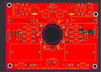
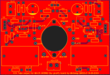
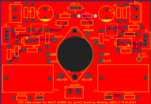
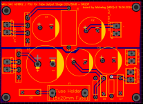
Here we go, gerbers for grunfs' CCS tube output and a quite raw PSU.
Today I'll be testing the old boards, just in case.
However these are perfected.
Today I'll be testing the old boards, just in case.
However these are perfected.
Attachments
Was pondering about this message, talking about ad1862, 2mApp output.I did tests with PCM1702, unfortunately not with TDA1541. I kept the 100R for years until I remembered to try a lower value. First I went to 75R and got a wow and then 50R and an even bigger wow 🙂
The difference in the sound was really noticeable especially with the 50R, the tube used was the 6S4P.
If it is an ECC88 and a current of +/-1mA(AD1862) and if we use only 25R for the Riv, the output voltage will again be 1.3Vp-p which will be quite enough for someone who has a preamp in the system. TDA1541 with the same Riv will have 2.6Vp-p with ECC88.
I don't have a preamp, so I drive the amplifier directly with the DAC, and that's the reason why I use tubes with a higher gain, 6S4P and now 6HM5 with a mandatory output buffer. However, as two more PCM1702s are arriving soon, so the ECC88 comes into play again, with four PCMs I could have an output voltage of 4Vp-p to 7Vp-p with a lower THD.
What about using a very low Riv (20~47) and a high mu tube, say 6n2p? I've full stash of 6n23p and I love them, but am also doubtful about hearing all this difference in thd... We're talking about decimals
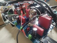
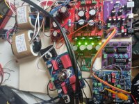
Wired, powered on...What happened with the ECC88 + CCS pcb's - did You try them ?
Asking beacuse You have them made.
It is leading me to tears 😭😭😭
Never heard my system sounding with this delicacy, finesse, depth, precision, it's something I can't describe with few words...
Miro, Grunf, you're the GOATs!!!! (Pardon Grunf, perhaps Miro a little more in this particular case)
It's moving.
È commovente, ho i brividi, non vorrei mai fermarmi di ascoltare, è una roba incredibile, tonight I could pass on football Italy -Albania to listen to this...
Attachments
Trafo Here
https://a.aliexpress.com/_EzfyfzZ
Tubes, this is a 6n23p-ev of sovietic Age (silver getter, to whom it may concern 😉 ).
At your side of the pond, a 6dj8/ecc88 would be easier to find...
The beauty of that board is that you can use different tubes (I'd like to experiment with a lower Riv and a 6n2p (12ax7 or ecc83)) just by biasing them with the ccs pot (took on purpose that trafo that spits out an higher b+), and a convenient cathode resistor, but this is for the future.
You can go easily with the schematic in previous pages, for tubes in Canada I don't have any hint, perhaps tubedepot in the US, whicj has also a variety of ussr tubes.

A simple question. My transport has I2s output. Can I feed this DAC directly?
CD Box RS2 T
Regards,
Dan
CD Box RS2 T
Regards,
Dan
I does accept I2s directly, but since your transport is using HDMI as the physical interface, you're going to need an HDMI > I2S converter/extractor like this:EBay HDMI>I2S converter
which, all things considered, isn't a bad option. You just can't do it directly from your transport.
which, all things considered, isn't a bad option. You just can't do it directly from your transport.
- Home
- Source & Line
- Digital Line Level
- DAC AD1862: Almost THT, I2S input, NOS, R-2R