Due to self-oscillations, you have depletion mosfets and ECC88 which is problematic itself.Hey Grunf, thanks for your valuable input. Just for me, why is important to miniaturize CCS traces?
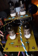
Gate stoppers and grid stoppers must be next to the gate or grid. The same applies to the high-ohm resistors in CCSs. Heating performed directly with the wires, with the mandatory small inductor in series and 1nF ceramics.
And in the end, all because of better performances.
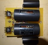
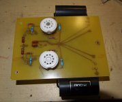
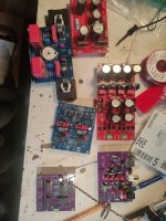
The photos show the I/V stage with 6S4P and CCS with one DN2540 (12 years ago).
Attachments


Well, it's not, I stick to the old proverb; as much money as much music 🙂 .
Otherwise, this is a simplified version of the regulator that I used for tubes and it really does a great job, the difference is quite audible if I compare it with classic HV power supplies and regulators.
Otherwise, this is a simplified version of the regulator that I used for tubes and it really does a great job, the difference is quite audible if I compare it with classic HV power supplies and regulators.
I suppose you forgot the attachment... However if you've ever done Gerbers, they would be more appreciated 😉
Ah wow, i thought you were attaching a simplified version 😁
Well, if THIS is the simplified one, I can't imagine what the complex one looks like 😁
Well, if THIS is the simplified one, I can't imagine what the complex one looks like 😁
DAC702 update
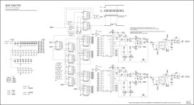
I tested the first schematic, it works but not "great" because present are audible glitches when the volume is very low
In this case the easy way is not possible, it was to be expected. Sample-hold circuit was added with digital control circuit.
I will have to test it somehow on the first prototyping board, so things are getting a little complicated 😎
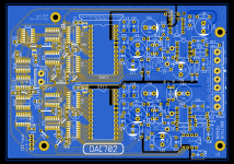
If the test succeeds, this will be the result.
I tested the first schematic, it works but not "great" because present are audible glitches when the volume is very low
In this case the easy way is not possible, it was to be expected. Sample-hold circuit was added with digital control circuit.
I will have to test it somehow on the first prototyping board, so things are getting a little complicated 😎
If the test succeeds, this will be the result.
Attachments
@zoom777 This trimming is for testing purposes. So far what I tried the offset is almost impossible to set with standard multimeter, in fact, it is almost zero from factory. It will be a very fine tuning which is probably useless for practical use. Imagine that based on datasheet you need set with offset trimmer TR3 (TR4) voltage 0.000305mV on tpL (tpR) 🤣 You need a precise multi-digit multimeter for that. The same is for TR1 (TR2), where the maximum positive voltage exact 10.000000V on tpL (tpR) is set, or the maximum negative voltage -9.999695V. So we are most likely talking about setting the precision on one bit here, what is 0.000305mV. I made a simple code for arduino with which you can set these values (the code actually sends bits via I2S ... it is also applicable for AD1862, but here it would be an even more precise setting, since there it is 20-bit precision, and ultra-precise trimmers are needed - again useless for the practical use 🤣)
I haven't fully tested it yet, because I'm waiting for the parts so I can see if the changed digital input with the sample-hold circuit works at all 😊
I haven't fully tested it yet, because I'm waiting for the parts so I can see if the changed digital input with the sample-hold circuit works at all 😊
Hello friends, I've looked back in the thread in a quest for answers but...
Ok, if someone has the patience to drop me a 2-liner for my questions... I guess everyone not acquainted with the digital world would benefit...
Thank you (for the moment 😊)!!!
Mike
Ok, if someone has the patience to drop me a 2-liner for my questions... I guess everyone not acquainted with the digital world would benefit...
- what's the function of the shift registers? Why 2 for data right and all 6 for data left?
- will be there a significant audio improvement with and without shift registers?
- in the inputs board to i2s, what's the difference between the different decoders i2s, lj, RJ (read there is a change in bck, but will this be correctly interpreted by out ad1862?)
- what is that optional msb adjust, for which we are leaving the six resistors out?
Thank you (for the moment 😊)!!!
Mike
http://pavouk.org/hw/audiosystem20/en_ad1865dac.html
- will be there a significant audio improvement with and without shift registers?
... it depends on the DAC, for AD1862 some people say that the sound is better if it comes directly from source device - for example jlsounds,,, I didn't recognize the difference 🙂 - in the inputs board to i2s, what's the difference between the different decoders i2s, lj, RJ (read there is a change in bck, but will this be correctly interpreted by out ad1862?)
... this is all about the specification of that chip, how the data is aligned - what is that optional msb adjust, for which we are leaving the six resistors out?
... I see, MSB adjust ... you need professional devices as it is about high precision, it has absolutely no effect on the sound, better skip this 😀
I created at least 3 different versions for AD1862, all can be found in the thread, but the most popullar is the one in first thread with 6 shift registers.
6 shift registers can storage 48-bit of data ... both channels are delayed by 13-bits for proper aligning (2 shift registers) + the whole second channel must be delayed (32 bit = 4 shift registers) ... when data are aligned and clocked into DACs, both DACs will be updated with the LRCK falling edge 😊
TDA1541 is much more complicated and out of scope to explain 🤣 ... try to simulate simple things in quartus, or in online tool falstad, or proteus and so on ... then gradually try to simulate more complex things and try to understand how the timings work (because the up/down bit does not mean that it will be correctly written by the clock --- first the bit must be present before the clock can write it) ... it's not easy, if it was like that everyone would do it 😀
Miro, thanks. That's more than enough for me. I like never stopping to learn, but this requires serious studying, it's not subject of a few lines.
Ok, when I'll build the tda1541 one, I'll ask for the input board whether it is i2s, lj or RJ 🙂
Are you electronics engineer for profession?
This should be have a great work for you, with all DAC variants, and the surrounding boards.
Let me express my sincere admiration.
Thank you Miro!
Ok, when I'll build the tda1541 one, I'll ask for the input board whether it is i2s, lj or RJ 🙂
Are you electronics engineer for profession?
This should be have a great work for you, with all DAC variants, and the surrounding boards.
Let me express my sincere admiration.
Thank you Miro!
@Michelag Thanks 🙂
There are better (easier) professions compared to electronics engineer, I don't have much interest in it at the moment 😀
However, it heavily depends on determination and passion, and also from the location 😉
There are better (easier) professions compared to electronics engineer, I don't have much interest in it at the moment 😀
However, it heavily depends on determination and passion, and also from the location 😉
Seems like another abandoned project 🙁 DAC702 still have some digital noise on the output. It will not be a good chip for audio use ... there is a similar digital noise problem as with discrete DACs and I haven't found a way to eliminate it. In my opinion the internal switches are not immune enough to digital interference and that's where the noise is transferred to the current output. Placing digital filters or analog filters on the output is not the way.DAC702 update
I tested the first schematic, it works but not "great" because present are audible glitches when the volume is very low
In this case the easy way is not possible, it was to be expected. Sample-hold circuit was added with digital control circuit.
I will have to test it somehow on the first prototyping board, so things are getting a little complicated 😎
If the test succeeds, this will be the result.
If someone has an idea or know how to deal with this digital noise issue, I can send the project files 🙂
So the candidates for excellent audio remain AD1862, PCM63, TDA1540, AD1865, there is a lot to choose from 😉
- Home
- Source & Line
- Digital Line Level
- DAC AD1862: Almost THT, I2S input, NOS, R-2R