
@ra7 TDA1541 is not bad, but TDA1540 sounds somehow better in my opinion 😎 (we are talking about the same topology (the same power supplies) and the same data decoding system with CPLD) 🙂
The next testing boy will be the DAC8811 😊Agree with Zoom, thanks for trying to get great sound from this obscure chip, Miro.
There are plenty of other rabbit holes to dig deep into with proven performance 😁.

Finally someone that thinks like me... My Philips cd104 and 204 say thanks...@ra7 TDA1541 is not bad, but TDA1540 sounds somehow better in my opinion 😎 (we are talking about the same topology (the same power supplies) and the same data decoding system with CPLD) 🙂
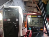
@lasercut Sorry for the bad pictures, but the dmm probes are stuck randomly, so the grey dmm shows the +-12V path, the orange dmm (right) shows the +-5V path.
To all, how shall I configure raspberry/Moode to play with USB? I mean what kind of DAC to put in it, 24/48 or 24/192, and what else?
Thank you!
To all, how shall I configure raspberry/Moode to play with USB? I mean what kind of DAC to put in it, 24/48 or 24/192, and what else?
Thank you!
Hey Michelag, let me answer to yourself: USB input, JP3 = SPDIF= 1&2, JP4=1, JP5=1;
On Moode side,
Output, USB device, as DAC generic i2s dac, mpd options dsd over PCM, Sox resampling to 24/192.
And also this works 😁
ReEdit: for DSD files, over PCM (also native works, if I could understand why), SoX resample 24/48, with 24/192 there's huge hiss
On Moode side,
Output, USB device, as DAC generic i2s dac, mpd options dsd over PCM, Sox resampling to 24/192.
And also this works 😁
ReEdit: for DSD files, over PCM (also native works, if I could understand why), SoX resample 24/48, with 24/192 there's huge hiss
Last edited:
Interested at this very good looking deviceMuch has been said about the BJT IV from Sergio :
https://www.diyaudio.com/community/threads/dac-i-v-measurements.395738/
https://www.diyaudio.com/community/...-with-very-low-distortion.217459/post-5756616
Knowing Sergio's competence in audio circuit design, I also want to find out.
Although the power supply voltage is not listed in the original schematics, those skilled in the art can figure out that it should be +/-20~24V to have good performance.
Scaling down to +/12~15V rails plus 2.8k Riv, and the distortion figures look rather different in simulations.
But simulation is not reality, so there is only one way to find out.
The prototype works first time as expected, with 12V rails.
So direct plug-in to replace opamp IV (MUST remove Riv and Civ first).
DC drift from cold to steady state in less than 3 minutes is a not-too-small 60mV.
But once stable, it stays well within +/-5mV.
All transistors are matched in this case.
This will now go to Ireland for comparative measurements, as well as listening.
When all is fine, and there is serious interest, we shall publish Gerber.
Patrick
.
Is there any news from Ireland
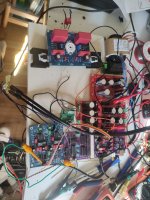
So Friends, approaching to the end of this project (yes enclosure still missing), and starting the next one (TDA1541... Or 1540? Or what?) I'm baffled.
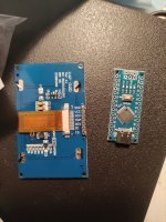
This is called ssd1309, and has 7 pins. Not only I don't have a clue about Arduino programming, but here I don't know how to wire things here (except G and Vcc 😉 )...
What I'd like to show is input (USB, coax, optical) and sample rate (and bitrate?)
To switch between USB/coax/toslink I think I will use a dpdt, nothing fancy. Although I populated Miro's input selector board, his USB/coax/optical board has just one i2s output, so no way using the input selector.
So, how to catch the i2s signal, communicating it to Arduino? And the inputs?
Sorry to monopolize the thread at this point, but this Arduino is Greek to me...
Thank you, mainly for the patience!
Attachments
approaching to the end of this project
What happened with the ECC88 + CCS pcb's - did You try them ?
Asking beacuse You have them made.
Few pages back I did post a project along the same lines, you can give it a try.So Friends, approaching to the end of this project (yes enclosure still missing), and starting the next one (TDA1541... Or 1540? Or what?) I'm baffled.
This is called ssd1309, and has 7 pins. Not only I don't have a clue about Arduino programming, but here I don't know how to wire things here (except G and Vcc 😉 )...
What I'd like to show is input (USB, coax, optical) and sample rate (and bitrate?)
To switch between USB/coax/toslink I think I will use a dpdt, nothing fancy. Although I populated Miro's input selector board, his USB/coax/optical board has just one i2s output, so no way using the input selector.
So, how to catch the i2s signal, communicating it to Arduino? And the inputs?
Sorry to monopolize the thread at this point, but this Arduino is Greek to me...
Thank you, mainly for the patience!
Post #8,276
For expanding the input option you can give the CPLD project a try.
Last edited:
What you have is an SPI based OLED, headover to chatgpt (if you have access to version 4 then it will be better) paste my code there and ask it to modify the code from ssd1306 I2C to SSD1309 SPI version, hopefully it will be able to modify the code.
Recently I have found chatgpt to be pretty good in helping with c, c++, python codes for various micros. Give it a try.
Recently I have found chatgpt to be pretty good in helping with c, c++, python codes for various micros. Give it a try.
Ok rehana, I'm giving it a try.
My question is, where to I have to solder the pins for SPI (MOSI, CLK, CS, DC, RESET) ?
Given that Chatgpt says
#define OLED_MOSI 11 // Pin SPI MOSI
#define OLED_CLK 13 // Pin SPI SCK
#define OLED_DC 9 // Pin DC
#define OLED_CS 10 // Pin CS
#define OLED_RESET 8 // Pin Reset
// display object
Adafruit_SSD1306 display(SCREEN_WIDTH, SCREEN_HEIGHT, &SPI, OLED_DC, OLED_RESET, OLED_CS);
const int lrclkPin = 2; // Pin LRCLK
const int usbPin = 8; // Pin input USB
const int coaxialPin = 9; // Pin input COAXIAL
const int bluetoothPin = 10; // Pin input BLUETOOTH
so, bluetooth is 10 (as CS?) coax is 9 (as DC?), etc.
edit:
WOW! I corrected him, and gave out
#define SCREEN_WIDTH 128
#define SCREEN_HEIGHT 64
#define OLED_MOSI 11 // Pin SPI MOSI
#define OLED_CLK 13 // Pin SPI SCK
#define OLED_DC 9 // Pin DC
#define OLED_CS 4 // Pin CS
#define OLED_RESET 8 // Pin Reset
// Crea un oggetto display
Adafruit_SSD1306 display(SCREEN_WIDTH, SCREEN_HEIGHT, &SPI, OLED_DC, OLED_RESET, OLED_CS);
const int lrclkPin = 2; // Pin LRCLK
const int usbPin = 10; // Pin input USB
const int coaxialPin = 6; // Pin input COAXIAL
const int bluetoothPin = 7; // Pin input BLUETOOTH
Interested at this very good looking device
Is there any news from Ireland
Hi all,
I'm afraid this particular IV is not completed yet - too many other rival projects! But I hope to get to it before too long......
Fran
- Home
- Source & Line
- Digital Line Level
- DAC AD1862: Almost THT, I2S input, NOS, R-2R