It is certainly not the place, but I had always wanted to understand more about that virtual ground concept with an operational amplifier and the "loopback" resistor. If indeed there is a resistor that is a passive part, the "passive I/V" sentence is certainly not the accurate words for such a tipology I surmise.
The plus input of the OPA is connected to GND. OPA will do everything so that the minus input is also at 0V, that's your virtual GND point. To achieve this, as the current at Iout goes positive, OPA will drive the output negative by as much as the voltage drop across the loopback resistor. When the current at Iout goes negative, the output of the OPA goes positive. In this way, the voltage at Iout is always 0V and gain=(-1). It's active I/V.
That's my view of things, if I'm wrong someone will correct me.🙄
That's my view of things, if I'm wrong someone will correct me.🙄
Last edited:

Hey guys,
I have a dumb question. How do you select/search on Mouser wires to connect:
- PSU + DAC
- i2s for USB controller + DAC
- DAC line output to RCA?
There are so many options and I cannot find anything.
Maybe, you have an example from your BOM?
I will appreciate any advice,
thanks!
I have a dumb question. How do you select/search on Mouser wires to connect:
- PSU + DAC
- i2s for USB controller + DAC
- DAC line output to RCA?
There are so many options and I cannot find anything.
Maybe, you have an example from your BOM?
I will appreciate any advice,
thanks!
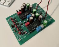
I just finished my PCM63 build. For some reason, I’m not getting sound from the left channel. I’ve flip flopped Dac chips + wiring and can isolate the problem to something on the board itself (DAC chips, PSU, IV, and I2S input all confirmed fine). Before I dig into more extensive troubleshooting, I thought I’d post pics here to see if it’s something obvious or known that I’m overlooking. Thanks!
Attachments
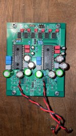
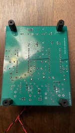
2nd picture, left channel only seeing one blue resistor on the bottom, maybe hiding behind center large cap. I also noticed on back a jumper on left channel that isn't there for right channel.
Thanks for taking a look. The jumpers are all there - I just put that one on bottom because I ran out of the 207 jumpers I had. All the other jumpers are the 0207 blue resistors you mentioned.

Will do, thanks for taking a look! In the meantime I reflowed the joints on the DAC IC pins. I also verified that all the power pins on the DAC IC are receiving correct voltages. I think you’re onto something with the input logic pins. I’ll touch those up in the morning and report back. 🙂
See the post #4022 from Vunce 😎 ... you can also buy something from aliexpress:Hey guys,
I have a dumb question. How do you select/search on Mouser wires to connect:
- PSU + DAC
- i2s for USB controller + DAC
- DAC line output to RCA?
There are so many options and I cannot find anything.
Maybe, you have an example from your BOM?
I will appreciate any advice,
thanks!
2.54 pitch: https://www.aliexpress.com/item/4000867583795.html
... or here both also the 5.08 pitch: https://www.aliexpress.com/item/1005001711075410.html
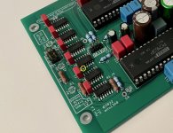
@codyt it is mostly the soldering, in your case I will bet on IC3, IC4, IC5, IC6 🤓
(not all pins are important and most of them are unused (the unused can be cut off before soldering 🤣 🤣 🤣 ), check only the important/connected pins based on the schematic)
(not all pins are important and most of them are unused (the unused can be cut off before soldering 🤣 🤣 🤣 ), check only the important/connected pins based on the schematic)
Hi Miro,See the post #4022 from Vunce 😎 ... you can also buy something from aliexpress:
2.54 pitch: https://www.aliexpress.com/item/4000867583795.html
... or here both also the 5.08 pitch: https://www.aliexpress.com/item/1005001711075410.html
sorry for my English.
I meant cable something like this 🙂
https://nl.mouser.com/ProductDetail/Vector/W28-6F?qs=asWOKBslL3cOrTSDGn1LoA==
Shall I buy any basic one?
BINGO – that did the trick! Thanks Miro!! Happy owner of a Miro PCM63 now 🙂@codyt Resolder these pins ... if it does not work, check all pins in input logic ICs 🙂
I use this silicone jacketed fine stranded copper wire in various gauges/colors for all my power and signal needs.Hi Miro,
sorry for my English.
I meant cable something like this 🙂
https://nl.mouser.com/ProductDetail/Vector/W28-6F?qs=asWOKBslL3cOrTSDGn1LoA==
Shall I buy any basic one?
https://bntechgo.com/bntechgo-24-ga...-flexible-24-awg-stranded-tinned-copper-wire/
Congrats to your new DAC 😎 ... now the TDA1541A? 🤣🤣BINGO – that did the trick! Thanks Miro!! Happy owner of a Miro PCM63 now 🙂
Sounds like a plan!Congrats to your new DAC 😎 ... now the TDA1541A? 🤣🤣
 What will be the PSU?
 I have not decided yet, but your idea of stacking the dac and psu looks too cool to reject. So i think i am very likely to use your psu design.
- Home
- Source & Line
- Digital Line Level
- DAC AD1862: Almost THT, I2S input, NOS, R-2R