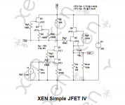
27R Passive IV + 100x JFET Gain Stage
Quite a few here loves passive resistor IV plus a high gain (tube) amplifier to bring the signal to say 2Vrms.
While many are using tube amplifiers, there is no reason why you cannot do the same with solid state.
I already mentioned earlier about the AD8429, which is also used in the Balanced Phono input stage by Salas.
https://www.diyaudio.com/community/...st-tht-i2s-input-nos-r-2r.354078/post-7138652
https://www.diyaudio.com/community/threads/chipomatic-balanced-input-riaa.331009/
But some people prefer tube- , or tube-like sound with a heavy dose of 2nd harmonic distortion.
It is well known that FETs are quadratic devices, similar to tubes and different from BJTs.
So how about a passive IV + a JFET gain stage ?
Using a 27R iv resistor, the AD1862 will creat 20mVrms at the output.
This requires 100x amplification.
I quickly put together one such schematics, quite similar to many NJFET phono preamps around.
1st stage is just a single-JFET gain block, though it looks complicated because of cascoding.
2nd stage is a simple JFET source follower with resistor biasing.
To make it a low-cost project for experimenting with, only obtainable devices are used (Onsemi J111 and J113).
Yes, there is an output coupling cap, and it has poor PSSR.
But it is very simple and easy to make.
The J113 needs cascoding for low distortion, hence the J111's.
And you will need a very quiet regulated power supply
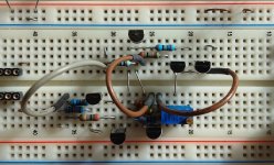
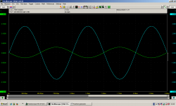
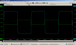
I put together a breadboard mock up on this Sunday morning.
Works first time.
Not serious, just for fun. 🙂
Patrick
Quite a few here loves passive resistor IV plus a high gain (tube) amplifier to bring the signal to say 2Vrms.
While many are using tube amplifiers, there is no reason why you cannot do the same with solid state.
I already mentioned earlier about the AD8429, which is also used in the Balanced Phono input stage by Salas.
https://www.diyaudio.com/community/...st-tht-i2s-input-nos-r-2r.354078/post-7138652
https://www.diyaudio.com/community/threads/chipomatic-balanced-input-riaa.331009/
But some people prefer tube- , or tube-like sound with a heavy dose of 2nd harmonic distortion.
It is well known that FETs are quadratic devices, similar to tubes and different from BJTs.
So how about a passive IV + a JFET gain stage ?
Using a 27R iv resistor, the AD1862 will creat 20mVrms at the output.
This requires 100x amplification.
I quickly put together one such schematics, quite similar to many NJFET phono preamps around.
1st stage is just a single-JFET gain block, though it looks complicated because of cascoding.
2nd stage is a simple JFET source follower with resistor biasing.
To make it a low-cost project for experimenting with, only obtainable devices are used (Onsemi J111 and J113).
Yes, there is an output coupling cap, and it has poor PSSR.
But it is very simple and easy to make.
The J113 needs cascoding for low distortion, hence the J111's.
And you will need a very quiet regulated power supply
I put together a breadboard mock up on this Sunday morning.
Works first time.
Not serious, just for fun. 🙂
Patrick
Attachments

Just a quick note on components.
Resistors can be 0.4W metal film (e.g. Dale RN55).
If you want to spend money (later), then Riv can be Vishay S102, or Caddock MK232.
Gate stoppers can be smaller and close to the gate pin.
I use Susumu 0805 SMD most of the time.
The 3k 1W should ideally be metal film (e.g. Vishay CFP1).
10µ film cap I would use WIMA MKS2 10µ // MKP2 1µ or 470n.
Should be very compact.
Patrick
0.1uF 400V at the output is too small (capacity and voltage). 2,2uF/630V as a minimum. The required capacity depends on the resistance of the next stage.
The output resistance of this SRPP stage is not very small, like with OPA for example. The capacity of the interconnect cable can become an important factor depending on the length of the cable.
I would also avoid this LC filter. I doubt it has a positive effect on the sound. And for these Miro DACs it is not even necessary.
Last edited:
Why 400VDC capacitor is 'too small", if the plate power is only 300VDC ?!
In steady state there will be 150VDC on it.
400/150= 2.7 times spare!
P.S. As for me, better to use 5687 or 6N6P.
(and to be clear, much better to use OPA1656 in I/V MFB configuration, but this is another story 🙂)
In steady state there will be 150VDC on it.
400/150= 2.7 times spare!
P.S. As for me, better to use 5687 or 6N6P.
(and to be clear, much better to use OPA1656 in I/V MFB configuration, but this is another story 🙂)
Last edited:
Build the 1.3, it is the most popullar and proven with great sound 😉Hi, folks! What AD1862 DAC version is better to make - 1.3 or 2.1?
Safety is the right word. If something unexpected happens, you can get 300V at the output. I know of a case where a 400VDC capacitor with a 250VDC power supply broke in tube preamp. It can destroy a transistor amplifier instantly. Capacitors are not perfect. That's why, to be safe, I always take double the voltage of the capacitor than the voltage of the supply.Why 400VDC capacitor is 'too small", if the plate power is only 300VDC ?!
In steady state there will be 150VDC on it.
400/150= 2.7 times spare!
P.S. As for me, better to use 5687 or 6N6P.
(and to be clear, much better to use OPA1656 in I/V MFB configuration, but this is another story 🙂)
As for the 6N6P, that tube has a big flaw. When you turn it on, it takes 2-3 hours to reach maximum sound quality, an eternity. And only those from the 60s of the last century sound really good. I've been building Aikido CF with that tube, and that's how it behaves.
I know of a case where a 400VDC capacitor with a 250VDC power supply broke in tube preamp
I worked for many years in Power Supply R&D at Philips, and I can say - if 400VDC capacitor broke from 300VDC, it was defective. Normal 400V film capacitor in good condition - will never fail even at 400-420VDC. for a short time, and at 350-380V continuously.
The only reason is the capacitor overheating.
Once I encountered the fact that the interstage polypropylene (85C max.) ICEL capacitor in a tube amplifier overheated and exploded.
Moreover, it was at 630VDC when the driver was powered from 250V - so more than twice the capacitor voltage did not help.
As for the 6N6P, that tube has a big flaw. When you turn it on, it takes 2-3 hours to reach maximum sound quality, an eternity.
I have never seen this with 6N6P, and even more so with 5687.
I had this only with 845, GM70 and 6C33C - sometimes 40-50 minutes was not enough there.
But with 6N6P or 5687 - a maximum of 5-10 minutes.
Yes, most likely the capacitor is permanently overheated in the tube preamp.The only reason is the capacitor overheating.
6N6P behaves like that in Aikido CF, at least the two I have and a couple of others I borrowed and tried. I don't have another device to test them, but I tried 6N1P-EV and Amperex 6922 in the same device (with other cathode resistors of course, I have 4 jumpers for that setting) and they didn't behave like that, they reach the maximum sound quality much faster (one hour aproximately).
If polypropylene 85C capacitor is so overheated, it doesn't matter it is 400v or 1000v ( at 300v power supply).Yes, most likely the capacitor is permanently overheated in the tube preamp.
I agree about 5687 as I've used it in a couple of amps (e.g. as output triodes in OTL amp for Stax earspeakers). It takes about 5-10 minutes to heat up properly.But with 6N6P or 5687 - a maximum of 5-10 minutes.
But you have to remember that some people have a different view on maximum sound quality 😉
But you have to remember that some people have a different view on maximum sound quality
Sure 🙂
That's why I mentioned:
but this is another story
As for me, I stopped using tubes in DACs many years ago, just in amplifiers, but different people, different opinion.
The sound becomes more open and beautiful over time from the start up as the device works (1-2 hour). It is a subjective impression. Not only did I notice it, but so did others. Each tube warms up nicely in 5-10 minutes, and that doesn't change later, there is some other reason. And it's not just for tubes, but for all devices more or less. Maybe my ears need 1-2 hours to stabilize. 😵
Last edited:
- Home
- Source & Line
- Digital Line Level
- DAC AD1862: Almost THT, I2S input, NOS, R-2R