
Happylistening, did you read the Loesch paper i linked in the thread about a circuitry with that tube and that chip (that talk about pcm63 and tda1541a etc as well)?
You should be happy with 100V for B+ and something 75 ohms if a lot of gain in your pre amp, to 100 ohms as I/V. Cathode 10 ohms? Hummm better to read the paper.
Put a Grunf reg for B+ et voilà
You can refine it better with a srpp, full tube or hybrid mu follower or even pure CCS.
You should be happy with 100V for B+ and something 75 ohms if a lot of gain in your pre amp, to 100 ohms as I/V. Cathode 10 ohms? Hummm better to read the paper.
Put a Grunf reg for B+ et voilà
You can refine it better with a srpp, full tube or hybrid mu follower or even pure CCS.
Last edited:
I prefer slightly higher supply voltages than 100V for B+. For Ua 80-90V, B+ 160-180V for E88CC.
Low voltage, low cathode resistor, less 100 ohms grid stopper if needed...c'est T Loesch philosophy ! Pick your poison 🙂
Smaller B+ smaller Ua, the tube goes into a less linear zone, THD increases. Maybe it sounds better that way, I don't know. I'm not a fan of THD, even if it was the famous 2nd harmonic. 😎
PS
Since the input voltage is small, the negative bias on the grid is not a problem, it can be small. And the anode current through the E88CC to be around 10mA to make it sound as good as it can.
PS
Since the input voltage is small, the negative bias on the grid is not a problem, it can be small. And the anode current through the E88CC to be around 10mA to make it sound as good as it can.
Last edited:
I also had very good experiences with the Tesla 6CC42 (5670/6N3P equivalent, only much better sounding) in the Aikido line preamp. Mu is 36.
Another advantage of those tubes is that they are significantly smaller in height than the E88CC. Anode voltage 100V, B+ 200V, anode current 7mA. Voltage gain in Aikido is 18x, reduced to 3x with NFB. With NFB they sound even better, and the gain is normal for a line preamp. 😎
Another advantage of those tubes is that they are significantly smaller in height than the E88CC. Anode voltage 100V, B+ 200V, anode current 7mA. Voltage gain in Aikido is 18x, reduced to 3x with NFB. With NFB they sound even better, and the gain is normal for a line preamp. 😎
Last edited:
https://www.mvaudiolabs.com/tubes/tube-data-library/e88cc/Smaller B+ smaller Ua, the tube goes into a less linear zone, THD increases. Maybe it sounds better that way, I don't know. I'm not a fan of THD, even if it was the famous 2nd harmonic. 😎
PS
Since the input voltage is small, the negative bias on the grid is not a problem, it can be small. And the anode current through the E88CC to be around 10mA to make it sound as good as it can.
I prefer slightly higher supply voltages than 100V for B+. For Ua 80-90V, B+ 160-180V for E88CC.
This is just an idea for now, it needs to be tweaked a bit more, but it could be a good solution.may I ask normally how many gain
Hi grunf,
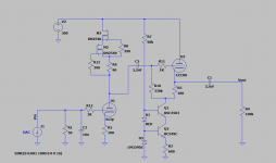
the ad1862 dac chip provide 1ma current, using 50ohm IV resistor, 50mv output signal will be provided. If 1.5vrms output required and using ecc88, which Vdc value of HT anode supply and ohm value of cathode resistor, the 6.3Vdc of filament provided.
Thank so much
Happy
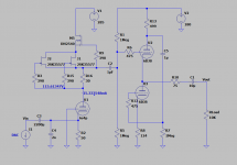
One ECC88 per channel, one half for the ground grid and the other for the buffer.
Attachments
50ohm I/V resistor and current +-1mA, then you have max. 100mV PP equal to 35mV RMS at the output. You will need a lot of voltage gain to get to about 2V RMS (57x). For that you need something like ECC83, ECC81, 6N2P...
In this case tubes like E180F or 6S3P-EV could be used ( Mu 50-60 depending on application ) ?
------
Does anyone have some schematics / examples with 6S3P-EV triode ?
What's wrong with the kiss?
No one bothering with datasheets and graphs?
14+mA per ECC88 triode ....... pretty much on too hot side
No one bothering with datasheets and graphs?
14+mA per ECC88 triode ....... pretty much on too hot side
6S4P and 6S3P are the same tubes, the only difference is that 6S4P is designed for ground grid and therefore has a different layout of pins and slightly different input capacities.In this case tubes like E180F or 6S3P-EV could be used ( Mu 50-60 depending on application ) ?
------
Does anyone have some schematics / examples with 6S3P-EV triode ?
I used the 6S4P for a long time, it's a great tube.
Attachments
14mA is not a problem at all for ECC88, it only plays well at higher currents, 10mA is too little to get the maximum out of it, but at higher currents there may be problems and it should be treated like an RF circuit. DIYers can fall into that trap and then say that the ECC88 plays worse at higher currents.What's wrong with the kiss?
No one bothering with datasheets and graphs?
14+mA per ECC88 triode ....... pretty much on too hot side
And it's easy when you can change them like socks 🤣
Attachments

That pretty much agrees with what I wrote. It is unclear to me how to practically implement Ia=6mA and -8.5V grid voltage. A very high B+ there. I would like to see it practically through some schematics. They did not provide a diagram of the assembly in which the measurement was performed.
Last edited:
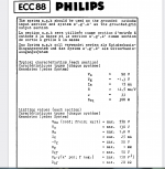
The tubes have specific anode curves and other important datas.
Design must be exclousively be with this datas. For each specific tube model.
.
Totally wrong way, repeating for decades, is guessing.
followed with generalisation, and wrong persumptions.
It is a real mistery 🙁
"No one bothering with datasheets and graphs"
.
inspire of that it is not a rocket sciense to choose, calculate, and build
a very good design within already present and given manufacturers datasheet informations.
for needed purposes in the equipment
.
this is not complete information set because it is not stated amount of input level signal, input source resistance, anode load, load at the output and other factors that impact the performances.That pretty much agrees with what I wrote. It is unclear to me how to practically implement Ia=6mA and -8.5V grid voltage. A very high B+ there. I would like to see it practically through some schematics. They did not provide a diagram of the assembly in which the measurement was performed.

- Home
- Source & Line
- Digital Line Level
- DAC AD1862: Almost THT, I2S input, NOS, R-2R