maybe you can try usb port from ROCK 1st to see whether the problem on rpi or usboveri2s boardOK. All the details of my current setup (please forgive me as I am still learning what is relevant and what not)
Roon ROCK Server via Roon bridge (RAAT) to RPi running RoPieee as Roon Endpoint
USB from RPi to JLSounds USBoverI2Sv.iii configured for AK4490 (B1 and B3 jumped, no R1)
JLSounds USB side powered by USB, Output side powered by 5V from Miro PSU1.
Miro PCB V1.3 DAC AD1862 shift registers installed and LM6171 OpAmps
PSU1 powering DAC and output side of JLSounds card
Issues (from first post)
1. Some scratchy noise at idle
2. Single loud pop when music starts playing first after power up of DAC (only after power cycle)
All of the above (not including the DAC) had been previously running without issues driving an AK4493 DAC (via I2S).
More specific I cannot be 🙂
Again: thanks for the help.
Mike
Confusion is all mine it seems. I'm running V1.3 DAC board (including registers) not the JLSounds stack. I found and read Post 617 but may have misunderstood. I followed Miro's advice in that post including configuration of JLS jumpers. But now on reflection I need to follow Post 2225 including R1 on JLS H1. Have I got that right?
Sorry for the confusion with the post 2225 (this is without shift registers, I did mistake in the "shortcuts".
Use the configuration from post #617 without R1. Be sure you will connect the GND (H3:14...) ——> GND DAC.
... for the RPI follow hints from all members because I have almost zero experience with RPI 🤣
The story of the folded cascode CEN IV continues here :
https://www.diyaudio.com/community/...-cen-iv-with-fixed-rails.389776/#post-7109978
Patrick
https://www.diyaudio.com/community/...-cen-iv-with-fixed-rails.389776/#post-7109978
Patrick
Here's a project I've recently completed.^^
Volumio3 - Raspberry Pi4 (2G RAM)
Miro's AD1862 R2R DAC with Tube I/V stage, and Linear Power Supply
8.8" IPS Display (1920x480)
Aluminum front panel (6T), steel case, wood case


Volumio3 - Raspberry Pi4 (2G RAM)
Miro's AD1862 R2R DAC with Tube I/V stage, and Linear Power Supply
8.8" IPS Display (1920x480)
Aluminum front panel (6T), steel case, wood case
Beautiful work on your streamer, Soonmo! What type of tube output stage is in there?
Nice looking preamp also, discrete circuit inside or opamp based?

Nice looking preamp also, discrete circuit inside or opamp based?

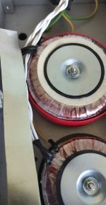
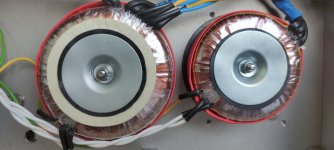
I cringe when I see inside the box wires everywhere with this no filtration concept.
Crossing of wires - like ikebana with this do not work - or drain in oscillations all together this.
The wires must be - 3-4 cm between all PCBs - separate modules with metal partitions.
Technical bottom, subchassis, mumetal shielding on transformers......key wires below...running GND via NTC to screw...


the mumetal board (with all postage and VAT) costs the same as both transformers 🤣
https://www.ebay.com/itm/274203420962
Crossing of wires - like ikebana with this do not work - or drain in oscillations all together this.
The wires must be - 3-4 cm between all PCBs - separate modules with metal partitions.
Technical bottom, subchassis, mumetal shielding on transformers......key wires below...running GND via NTC to screw...


the mumetal board (with all postage and VAT) costs the same as both transformers 🤣
https://www.ebay.com/itm/274203420962
Hey guys would someone be so kind and give me some pointers, because for the life of me I can't find any useful information about troubleshooting native DSD playback. I downloaded some sample DSD64 files, but cant get them to play normally. I only get white noise in one channel and very low background music; the other channel is dead silent. I know a lot things is involved in playing DSD especially in my setup (ROON) but for start I would only want to know basics 😀 So are these older DAC chips or this Miro pcb design we are discussing in this thread in any way a limiting factor of playing DSD or is the limiting factor USB to i2s board (and other equipment involved) in my case jlsounds which supports up to DSD512... This would be the start just to see if this is something it should work and I can pull some more hair from my balding head 😀
And in case anyone is wondering it is not that I need DSD it is just that it does not work and I have a strong urge to repair this even if I would never use it again, but I would sleep so much better... 😀
And in case anyone is wondering it is not that I need DSD it is just that it does not work and I have a strong urge to repair this even if I would never use it again, but I would sleep so much better... 😀
So are these older DAC chips or this Miro pcb design we are discussing in this thread in any way a limiting factor of playing DSD
DSD is a one bit file format suited to one bit delta sigma noise modulation DACs. Others think DSD was just a Sony marketing gimmick. Nearly all DSD are created from PCM multibit format needed to allow mixing.
Although DSD files are huge the inherent SNR etc is not usually commensurate to PCM.
These "old" R2R mutlibit DACs run exclusively on multibit PCM. You could think of them as an intrinsically more sophisticated DA architecture then one bit noise modulation.
Solution: Miro DAC + PCM = 🙂
Well the most simple answer I could have wished for, now I can go to sleep peacefully 😀 I was searching google for DSD and AD1862 but could not get any answers from google that would ease my mind.
Useful ToolsI can't find any useful information about troubleshooting native DSD playback. I downloaded some sample DSD64 files, but cant get them to play normally.
https://www.sonore.us/iso2dsd.html
https://www.sonore.us/dsd2flac.html
https://www.videohelp.com/software/sacd-extract
This can also be done manually from terminal
C:
sacd_extract -2 -s -C -i blabla.iso

cd blabla

for i in *.dsf; do ./dsf2flac -i "$i" -scale=5 --samplerate=192000 --bits=20 "${i%.*}.flac"; done

rm *dsf
Last edited:
I like the look, the concept and the tube output. But those "Audiophiler" red capacitors from China, throw it out immediately and get something proven. I got them with some tube kit, I've never heard anything worse in my life. It immediately ended up in the garbage can, the same day. I don't think it's even polypropylene, who knows what's inside and what the breakdown voltage is.Volumio3 - Raspberry Pi4 (2G RAM)
Miro's AD1862 R2R DAC with Tube I/V stage, and Linear Power Supply
8.8" IPS Display (1920x480)
Aluminum front panel (6T), steel case, wood case
Since I am rolling opamps in my new DAC 1862, I began to think some opamps might not like the 2000 pF cap from inverting input to ground (recommended on the AD797 spec sheet) as much as others. So I switched them to 890 pF caps (what I had) and they all seem happy now...and it sounds good. Has anyone else actually tried 2000 pF vs 1000 pF caps vs no cap?
1) Interesting. That AD797 application diagram, no doubt, assumes use with an oversampling filter chip prior to the AD1862. Such filter chips additionally provide EQ for the famous -3.16dB@20kHz high-frequency response droop suffered by NOS operation. Without droop correction, the cut-off provided by a 2000pF filter cap. may become audible, when via OS, it may not be. That’s just a guess.…I began to think some opamps might not like the 2000 pF cap from inverting input to ground (recommended on the AD797 spec sheet) as much as others. So I switched them to 890 pF caps (what I had) and they all seem happy now...and it sounds good. Has anyone else actually tried 2000 pF vs 1000 pF caps vs no cap?
2) When you say it sounds good with the cap., are you saying that you feel it sounds better than without the cap.?
Last edited:
https://www.diyaudio.com/community/threads/new-unused-ad1862n-and-ad1865n-j-dac-chips.368012/Where can you still find those AD1862 DAC-ships today?
We tried the cap between inputs with the OPA1611 in a matching setup for PCM1704.
Distortion became horrible as measured by an AP 2722.
So we removed the cap immediately.
https://www.diyaudio.com/community/threads/any-project-with-pcm1704.325249/post-5810069
https://www.diyaudio.com/community/...865-output-stage-question.348728/post-6063070
Patrick
Distortion became horrible as measured by an AP 2722.
So we removed the cap immediately.
https://www.diyaudio.com/community/threads/any-project-with-pcm1704.325249/post-5810069
https://www.diyaudio.com/community/...865-output-stage-question.348728/post-6063070
Patrick
Thanks, for providing that response. I’m not surprised. As you know, adding shunt capacitance to the inverting input of an op-amp causes phase-shift delay at the amplifier’s critical feedback control node. Maybe that was causing the severe distoriton you heard? Anyhow, compensation can stabilize such circuits, but makes a simple to implement pre-filtering solution, less than simple to design. In the AD797 DS I/V application diagram which we’ve been referencing, there is a parallel, two element feedback path (82pF in series with 100R) to maintain stability with 2000pF of shunt capacitance hung on the inverting input of the AD797.We tried the cap between inputs with the OPA1611 in a matching setup for PCM1704.
Distortion became horrible as measured by an AP 2722.
So we removed the cap immediately.
https://www.diyaudio.com/community/threads/any-project-with-pcm1704.325249/post-5810069
https://www.diyaudio.com/community/...865-output-stage-question.348728/post-6063070
Patrick
- Home
- Source & Line
- Digital Line Level
- DAC AD1862: Almost THT, I2S input, NOS, R-2R