Hello,
Autum trees colors are pretty in Tokyo 🙂.
Yes your traffo secondaries voltage choice is ok : no center tap for the super reg pcb board.
You should not have problem in your town & country to find excelent R-Core power traffo with a primary voltage made for your country.
All what you need first is to have two AC secondaries for the digital side: one for the dac pcb +/-5V DC and the other +5V DC for the non isolated side of the JLSound board (2x5V to 2x9V AC secondaries to feed two regulators) and a 12V to 15V AC secondary for the 12V DC side of the pcb & oaps (analog side).
Notice there are straps on the voltage rail on the main dac pcb. It's for instance if you want after makes some refinments : a secondary for the 12V side of the dac chip with one reg and another secondary and reg for the oaps , that permits to use also the two secondaries of a 2x12V VAC traffo !
Notice some operational amplifier talked in this thread can handle 5V and in this scenario you of course need only 5V to 9V AC secondaries. 5V to 9V is in relation to what choice you have in the shop or on hands at home, the regs output has to be of course 5V and the pcb heatsinks can dissipate easily a 9V AC power traffo.
Last edited:
Also,another transformer (+5v,0v) for I2SoverUSB board
is no problem?
The pcb needs +5V DC, most of the regs inputs are made for +5V/-5V secondaries so not for zero V center tape secondaries traffo which are marked +5V/0/-5V.
The super reg PCB outputs -5V/zero (ground)/+5V for the miro pcb dac board, but the JLSOUND pcb is needing only a +5V.
So if you use a power traffo with two 5V AC secondaries (2x5V VAC) : you can use one +/- 5V secondary for the super reg that outputs -5V/0/+5V DC to feed the miro dac board and the other secondary for another reg board that output a +5V DC only.
Last edited:
Thank you so much for explanation.
Do you recommend if I order 80VA for 4 secondaries
(+-5V, +-9v, +-12v, +-12v)
Do you recommend if I order 80VA for 4 secondaries
(+-5V, +-9v, +-12v, +-12v)
30VA should be quite enough but no problem to have more VA.
2x5V or 2x6V or 2x9V is certainly easier to find with 2x12V for a standalone power traffo in an electronic shop (Hakihabara?).
2x5V or 2x6V or 2x9V is certainly easier to find with 2x12V for a standalone power traffo in an electronic shop (Hakihabara?).
Thank you.
At phenix Rcore transformer,
I can custom order for 4 secondaries from minimum 80VA.
At phenix Rcore transformer,
I can custom order for 4 secondaries from minimum 80VA.
I find a 2x6 VAC will be more universal and a 2x12 VAC. (you always have to X 1.4 to have the non loaded output if I remember well, a little less with R-Cores)
80VA more than enough.
Ask Miro's confirmation for his Super Reg pcb before. but they are very low drop reg chips so it should be OK.
80VA more than enough.
Ask Miro's confirmation for his Super Reg pcb before. but they are very low drop reg chips so it should be OK.
Last edited:
Hello Miro.
Thank you for this DIY DAC plan.
I had been dreaming if I can build DAC,Amp,
for long time.
Do you recommend super reg from DIYaudio store
or something else?
Thank you for this DIY DAC plan.
I had been dreaming if I can build DAC,Amp,
for long time.
Do you recommend super reg from DIYaudio store
or something else?
Thank you for your help and information.I use a small 15VA, Telma 2x12vac secondary. it works fine for the PSU2.
the heat sinks of the 5V output rails must be very hot ?
Not too bad, think it's about 40 degC.
I had it running for few months on Psu2, so far so good.
@Tamra, you should give it a try, since the Psu2 pcb is coming your way
Last edited:
+1 for the PSU2 : PSU 2: LT1963A/LT3015 - Tested: #1461 + values correction, 2R2 resistors on power rails took from the first page of this thread that is always updated.

@tamra
I will recommend you one of my regulators.
Either PSU2 as discussed above with the values correction. Add there 2R2 resistors on power rails (either on the DAC pcb instead of J1-J13 jumpers, or just 2R2 resistor on each power wire (+-5V and +-12V)).
Or PSU1, which is also very good. The main advantage of PSU1 is the stability with a high output + very low-esr capacitance (with regulators from onsemi: MC7812/MC7912 MC7805/MC7905) -- that means no additional corrections are needed 😉
Well, transformer for your country ... In my opinion you can still use 12V + 12V transformer, like this R-Core from ebay: 115V/230V 30W R-Core Transformer for Audio AMP Amplifier Preamps DAC 12V+12V | eBay
The calculated output voltage after filtration is 14.7V (measure it please). The minimum expected voltage for PSU1 is 14.5V (if it is less, you will need another transformer) 🙂
The minimum voltage for PSU2 is 12.5V after the filtration, therefore this 12V transformer is enough (because 14.7 is calculated with the factor x0.87 for your country as you mentioned)
Thank you Miro.
I would like to buy PSU2.
Also I want to feed clear +5v to I2SoverUSB board.
Dose it make sense if I have another +-5v secondary or just
Share from PSU2?
I don't mind if I pay extra money from Japanese Rcore tranie.
I would like to buy PSU2.
Also I want to feed clear +5v to I2SoverUSB board.
Dose it make sense if I have another +-5v secondary or just
Share from PSU2?
I don't mind if I pay extra money from Japanese Rcore tranie.
The network I am currently using is similar to the single AD844 version in your link. The issue with the AD844 is that it often has instability issues with capacitors connected directly to ground, that in your link is 470pF. These issues stopped if a series resistor of > 50 Ohms was connected in series with pin 5, hence I use 100 Ohms between pin 5 and the capacitor.
I used a styrene 470p and didn't notice stability issues with the AD844. Do you mean I should add in any case the 100R as in the attached schematic?
Attachments
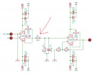
I used a styrene 470p and didn't notice stability issues with the AD844. Do you mean I should add in any case the 100R as in the attached schematic?
I would. I normally test devices and networks without local power supply decoupling in order to determine the sensitivity to instability. With a capacitor of value indicated (and mine are polystyrenes as well) it was found that oscillates occurred at pin 5.
In general if power supply decoupling becomes necessary to stop oscillation they are considered active of coupling power supply anomalies into the audio signal.
Thank you! But I still failed to completely understand it... Even if instability would occur without local decoupling caps: why is it not OK to use decoupling caps if that helps? So many datasheets recommend to add a cap to avoid instability, now I hear that this is kind of a "dirty" solution...?
Local supply decoupling caps close to the supply pins of the IC are a must if you want to keep your supply rails clean and prevent ground bounce. Both these things can lead to other mishaps, such as false triggers (0>1 and 1>0) due to noise on the supply rails or a shifted ground level.
- Home
- Source & Line
- Digital Line Level
- DAC AD1862: Almost THT, I2S input, NOS, R-2R