@jimk04
Datasheet of the WM8805 says "In hardware control mode the device can receive data only from RX0 ..." 😡
Input selector on a separated PCB could be the solution. MM74HC125MX ? Or something similiar which has 4 inputs and one output.
Datasheet of the WM8805 says "In hardware control mode the device can receive data only from RX0 ..." 😡
Input selector on a separated PCB could be the solution. MM74HC125MX ? Or something similiar which has 4 inputs and one output.
Thats a shame about only accepting RX0....a waste of it being multi input!
Don't worry Miro I guess there isn't a lot of interest for this and I don't wish to take your time. There are plenty of 'cheap ' spdif switches out there to try i suppose.!
Don't worry Miro I guess there isn't a lot of interest for this and I don't wish to take your time. There are plenty of 'cheap ' spdif switches out there to try i suppose.!
Hi, does anybody here know the best I/V resistor value for AD1862 ?
With 470 ohm and triode tube I get some distortion and have to adjust volume output in digital domain to compensate.
With 470 ohm and triode tube I get some distortion and have to adjust volume output in digital domain to compensate.
Do you mean passive I/V resistor value, or the I/V resistor in the I/V stage of Miro's Ad1862 DAC circuit?
EF86 in triode so about 18,5
For tube it is verg silent because of screen, and low distortion
Have now 68k anode R and 1k5 cathode R with 100uf bypass C
I expect it is the iv resistor value I am searching for. When I remove cathode capacitor it lacks some dynamics. I can try another anode resistor value.
Am planning another tube-bjt transistor scheme too.
Step by step i am getting where I want to be. But still OPA627 sounds best, that’s why I am asking around for best values
Last edited:
I am not a tube specialist but Mu here seems too much low for a 1 mA output...the I/V resistor value must be high hence distorsion maybe.
You should try to find Loesh Thermionic tube stage article and try tubes with a higher Mu around 35/40. For a resistor no higher than 200.
Try first 200 ohms and draw your shematic here or in the tube section. The C output is way too big imo.
Too much big grid stopper as well ?
An inexpensive E180F nos could be a place to start. 6dj8/ecc88. 6np23 EB....
Last edited:
I expect it is the iv resistor value I am searching for. When I remove cathode capacitor it lacks some dynamics. I can try another anode resistor value.
Am planning another tube-bjt transistor scheme too.
AD1862 isn't designed to drive anything other than an opamp's virtual earth. If you're hoping for good results with passive I/V then you may well be disappointed. Current output R2R DACs go decidedly non-linear when their output terminal isn't held very close to GND. I seem to recall there's an ADI paper explaining this, I shall look it out.
Hello , I got my AD1862 board from Paddy Garcia. Very happy.
I would also to make a Tube Output stage instead of OPamps.
Please help.
Thank you
I would also to make a Tube Output stage instead of OPamps.
Please help.
Thank you
You can acheive that with a tube as well...read t loesh paper
..of course an opamp is easier but has bad trade off as well as the feedback for most of them.
..of course an opamp is easier but has bad trade off as well as the feedback for most of them.
I will show some schematics of IV I am thinking of.
Indeed was a bit disappointed when I first listened to tubed resistor IV
Indeed was a bit disappointed when I first listened to tubed resistor IV
I have very good result with AD1865 DAC with 180R passive I/V resistor and SRPP tube stage. I used 6N23P tubes in bypassed SRPP configuration. AD1865 has +/-1mA output current too, so this circuit should be good with AD1862.
SRPP gain is about 24-25 so at the end I have 2VRMS output.
For better result you can add 1:5 transformer after the DAC chip and put the I/V resistor to the secondary side of the transformer according to suggestion of Sowter. In this case 620R I/V resistor at the transformer secondary side, and the DAC chip see 25R what is very close to the ideal 0R
That transformer idea is exactly also what I had in mind besides a hybrid tube transistor iv
Have some Nice transformers to try
Have some Nice transformers to try
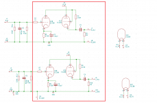
This is what I used with AD1865. Disregard the first part of the circuit, use only the components what are in the red rectangle. B+ is 225V
I used 1W AN Non Magnetic Tantallum resistors, with V-Cap Odam coupling CAP. Sounds very sweet.
But using a transformer between a DAC chip and the tube stage is a gamechanger. 🙂
I used 1W AN Non Magnetic Tantallum resistors, with V-Cap Odam coupling CAP. Sounds very sweet.
But using a transformer between a DAC chip and the tube stage is a gamechanger. 🙂
Attachments
Have 6x transformers and I guess indeed some amplification is needed after transformer. Thanks for the info !
I also like the idea of a transformer. I have a ANK Kits Canada AD1865 Dac kit 4.1 and it has such a transformer. I am making AD1862 now and want to make tube output stage. I like the discussion this is what I needed.
One question, on the AD1862 Dac PCB where exactly is the Line out for left and right channel can somebody guide me? It must be somewhere before OPamps? Thank you
One question, on the AD1862 Dac PCB where exactly is the Line out for left and right channel can somebody guide me? It must be somewhere before OPamps? Thank you
- Home
- Source & Line
- Digital Line Level
- DAC AD1862: Almost THT, I2S input, NOS, R-2R