@diyiggy
One SOIC version exists 😀 ... well, only single opamp version with 1cm decoupling wire, which is silly 😱 But one can scrap the solder mask and do a closer decoupling 😀
Yep I know, it must exist 🙂 . I still think a huge step will be to split the I/V from the buff stage, but who is listening to me in this thread... nobody 😉
The buffer would be easily possible with dual opamp package where one half is the I/V and second half is the buffer - I'm afraid of interference in dual chips with non-separated power supplies 
On the other hand, the buffer can be possible with two single opamps 🙂
On the other hand, the buffer can be possible with two single opamps 🙂
I prefer the single opamp as buffer then so you can choose the opamp for each stage. A fast opamp as I/V and another with better drive load capabilities as buffer. But for simplicity sake (wich I like) it could be better to use only one opamp. I ordered this dac in Dil opamp layout in special to try different opamps
Remember the LM6171 is not bad at all but the ths4031 sounds more live like and involving, better hearable stereo effects and more dynamic. Maibe a very small tick of ‘willdness’ in music but I don’t like the laid back soundstage of the LM. It is a right combination of all components just like cooking.
On the other hand with the LM6171 I discovered a sort of resolution in bass response I have never heard before, bass can have layers.. makes a good drive opamp in subwoofers ? 😀
Last edited:
On the other hand, the buffer can be possible with two single opamps 🙂
like for instance an opa861 as I/V and a cool 5V buffer after (while not ever needed according the load of the pre with it) : single channel oap as buffer or the opa 861 in reverse conf for that purpose as per Rogic shematic (Vunce pcb but without feedback cap on the late as I inputed in the thread already)
What are the cool "to do all" single channel buffer oaps that sound good today ?
Is a double 1656 (one for the Left and one for the Right) but using a single channel in it is good enough for a buffer or the there are problems yet due to his double channel architecture despite firering one side only?
I liked the opa2608 long time ago, but maybe it is a little obsolete these days ? (and the bass is not so accurate)
Last edited:
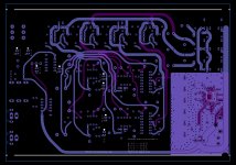
I used to have (and still!) something similar to this dac. It's based on pcm56. We have a small diy group, while sharing some ideas about old dac chips we decided to design something with pcm56. This was three years ago.
Long story short; If we use high value gain resistor sound becomes tiring, anything higher than 1.5kohm was a drawback. As I see 1862 has the same current output value as pcm56 and similar other dac chips from same era.
Anyone has any measurement or feedback about this?
I attached old design we used for pcm56.
Attachments

A power supply question - does the AD1862 behave OK with the voltages turned on separately to each other?
eg if only the 12v supply is connected, or only the 5V for a while? I want to do some experiments with power supplies and I think I will only be able to turn on both separately so wanted to check there is no issue from those with experience here.
I ask because some other chips do not like this at all!
The only interrest having separate rail is to know if it's sounds better to you or not in relation to a certain layout. There is no reason to fire on a part of a chip not knowing if it sounds better while not being able to check it.
A switch, well a switch in itself is a passive part in itself that deserves not to be here.
Fo experiments you simply needs two boards, one as a reference, idem for the material you playback with for these experiments.
two cents, YMMV.
A switch, well a switch in itself is a passive part in itself that deserves not to be here.
Fo experiments you simply needs two boards, one as a reference, idem for the material you playback with for these experiments.
two cents, YMMV.
I think I stated my question badly. I want to know if I happen to apply only the 12v rails and not the 5v, or vice versa, will the ad1862 be damaged?
I can tell you that 1794 does not like this! So I thought it best to check
I can tell you that 1794 does not like this! So I thought it best to check
Catherine DAC preview
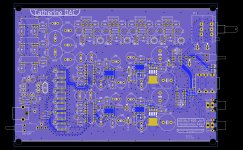
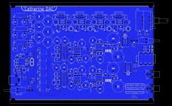
Catherine DAC originated as a project for my purposes 😎
It is AD1862 NOS almost THT DAC, completely USB powered with line-out and headphones amplifier, sourced with a decent power supply (800kHz DC-DC, CRC, LT1963/LT3015).
Headphones amplifier is the LME49600 buffer (sourced from the opamp = preferable opamp sound can be easily maintaned).
Integrated USB-I2S is the PCM2706 (only 44.1/48kHz 16-Bit, but any preferable xmos board can be "glued" to the PCB).
The PCB is 4-layer 140x200mm and easily fits into a cheap eBay enclosure (ebay.com/itm/333940934162) or any DIY enclosure.
Having a bug in such a larger PCB is not funny 😱, therefore I'll test it first. I'll share the gerbers after testing, it can take a while
The price for premium parts is quite high, but still better than delta-sigma premium filters
Attachments

Coooool 🙂
What if the relay was noy between the I/V but between the second oap and the headphone buffer ?
In others words, does the main DAC goal to drive a pre line not deserve its own non relay path ?
Relays can be sometimes seen as I2S/USB input choice for versatility (a merge of the two before designs)
Thanks, better and better DACs !
Last edited:
@diyiggy
The feedback needs to be disconnected.
Anyway, the headphones output is technically the buffer or preamp, which can theoretically drive the amplifier.
The feedback needs to be disconnected.
Anyway, the headphones output is technically the buffer or preamp, which can theoretically drive the amplifier.
My current setup, just finished miro's PSU. First fedex lost some parts then I realized I ordered wrong trimmers with pins in line so I had to do some bending to fit them but now everything is assambled and working.
I would like to try some discrete diy I/V stage and tube next...

I would like to try some discrete diy I/V stage and tube next...
Hi Ripster, close to my arrangement, just mirror inverted. This gives the opportunity to shorten the i2s cables, while keeping the transformers off the DAC board.
I am waiting for a crimp tool in oder to make shortest possible cabes for that. And waiting for an ICE inlet.
Like your usage of hot glue. Never seen that.
Cheers
I am waiting for a crimp tool in oder to make shortest possible cabes for that. And waiting for an ICE inlet.
Like your usage of hot glue. Never seen that.
Cheers
🙂 I like Pan FC on Ripster's board and the polyswitch is pretty cool
I like the short I2S connection from Ernst's board
I fear it is a Surimi Burson V6 plot 😉, so what oap did Burson copied to translate itr in discrete in this V6 ? NE5534 discretes like AUdioGrande or close ? Any info ?
I like the short I2S connection from Ernst's board
I fear it is a Surimi Burson V6 plot 😉, so what oap did Burson copied to translate itr in discrete in this V6 ? NE5534 discretes like AUdioGrande or close ? Any info ?
Last edited:
@diyiggy
The feedback needs to be disconnected.
Anyway, the headphones output is technically the buffer or preamp, which can theoretically drive the amplifier.
Is there a load input windows where the LM49000 is working better; e.g. 60 to 1000 ohms ? 32 ohms to 50 K ohms ? (numbers just took as an illustration)
What is please the purpose of the second LM after the first in the headphone aop input ? I never understood thetechnical purpose of several oaps after an I/V, it's above my head 😕, though see it often in the old cd players.
LME49600 deals great with impedances and capacitive loads 🙂
The second LM works together with LME49600 as the headphones amplifier (it has own feedback).
>>I never understood thetechnical purpose of several oaps after an I/V, it's above my head , though see it often in the old cd players.
It could be active filters 🙂
The second LM works together with LME49600 as the headphones amplifier (it has own feedback).
>>I never understood thetechnical purpose of several oaps after an I/V, it's above my head , though see it often in the old cd players.
It could be active filters 🙂
- Home
- Source & Line
- Digital Line Level
- DAC AD1862: Almost THT, I2S input, NOS, R-2R