Thanks, I can remove capacitors as nothing else will be connected to the preamp. capacitors may help to remove DC, if connecting to other sources.
Last edited:
I have designed a active volume control using lm4562 based on Self's preamp. Plan is to box DAC and Volume control along with raspberry pi into a compact streamer unit.😉
Any suggestions.
It looks overly complicated? Is your requirement just for volume control with no gain? If so I would just use a suitable potentiometer/switched attenuator and follow it with a simple buffer.
Maybe this would be a suitable buffer?
JG buffer - I2S over USB Audio
I've used this module before in exactly that scenario (volume control with no gain) and it sounded very good.
I've recently built something similar, a buffered passive 'preamp' but with vintage BUF-03 devices for the buffer stage - BUF-03s are really good in this context but are like hens teeth to buy. For the volume control I've had good results using an Academy Audio VCU module based on the Muses electronic attenuator chip - the remote control and numeric volume display are nice touches.
VCU | academyaudio
Thanks for your advice. This DAC project is for my second system. Have built a Bruno’s preamp for Okto DAC and it works well.
Was going to try my design which is effectively on similar principle. Never thought about dedicated volume control chips like MUSES. Will have a look at as remote control might be attractive.
Was going to try my design which is effectively on similar principle. Never thought about dedicated volume control chips like MUSES. Will have a look at as remote control might be attractive.
This is the buffered passive preamp I have built with the Muses VCU module.
Aunt Corey's Homemade Buffered Passive Preamplifier | Stereophile.com
Because it's a jfet front end on the BUF-03 I don't need to use the caps on the output of the VCU module, the same would apply to the JLSounds buffer I linked to above. I also don't use a cap on the input to the Muses module because I know I don't have DC present on the input signal.
Last edited:
A friend kindly loaned me a SEN pcb earlier in the week to try as an IV stage. I had a small stock of 2sk170, and I got suitable matches as outlined in the article and thread by EUVL. I started with some pp3 9v batteries to get it working and see how it sounded. This unit needs a floating supply, and batteries seem to make sense here. The sound is fantastic - I have ended up using 2 x 20V rechargeable battery packs from a drill. They will last a long time and can be charged easily. I am experimenting with some relay switching to see if it could all be done easily within one unit - these battery chargers usually have a 3rd wire (must be a current sensing circuit) and this would also need to be switched.
Anyway, I know 2sk170 are not that plentiful now, and the floating supply is tricky aside from batteries. But the sound is really great. In the article EUVL mentioned that 2sk117 could also work well, and these are cheaper and plentiful at a higher input resistance (25r) - would that work with the AD1862?
Fran
Nice weite up Fran.
I currently have LM6171. The ds states to decouple the psu with 0.01f ceramic at the pins and 2.2uf tantalum close by. Should I try this or is the 0.1uf film and 100uf we have on the board kind of overkill for all possible situations.? Would the 0.01 and 2.2 as per Ti a retrograde step from what we already have?
Thanks
@jimk04
0.1uF is perfect in audio aplications 🙂 ... lower values are suitable for higher bandwidth (far away from the audio range)
0.1uF is perfect in audio aplications 🙂 ... lower values are suitable for higher bandwidth (far away from the audio range)
To implement the SEN IV properly, you need minimum 4x matched 2SK170BL or 2x 2SK369BL per channel.
Otherwise the input impedance (which is not linear) is not low enough.
If you wish to use 2SK117, you will need 8x 2SK117GR per channel.
Incidentally all of them unobtaniums.
You also need minimum 18V floating supply.
People used batteries before, but they require knowledge in implementation to avoid RF pickup or oscillations.
Not for beginners. You have been warned.
If you still want to try, I advise reading through that thread carefully.
It will save you a lot of agony later on.
Patrick
Thanks Miro.
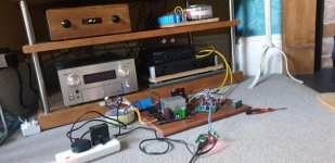
Another little trial this evening and I managed to get music via the XMOS board. First time I ever did this so it wasn't really a test of the dac more just to see if the system works. I had it working fine before with the 4118 spdif board. Seems the XMOS board into the 4118 wasn't happy but XMOS direct to 1862 is OK.
My system being Salas DCG3 pre>JLE 3255 pfb> XRK inspired transient perfect Ref monitors.
My other source is a reasonably well sorted Ian Canada based DAC streamer thing and and so the music material source was different with the 1862 but for the short time I heard it today it was very impressive.
Thanks again Miro.
Attachments

Nice work @jimk04!!
I would echo @EUVL words above - I have read that thread (zen, cen, sen its looong) twice now. There is much information in it and in the linear audio article that is a must to read. Particularly on the power supplies. I can sincerely endorse the words "save yourself a lot of agony later on"!!
If you are going to build it, then be sensible and use 4 x 9V batteries to see if you like the sound. Only after that would you think about a different solution.
Superb thread and projects, both AD1862 and AD1865, guess I ll finally find some use for my inventory of DACs.
Will be making the PCBs with some amendments, will use LEM49720HA instead of LM4562 or OPA627. I want to put the last of LME49720HA to use. I will share the PCB design once I am done with it before sending it to PCBWAY for fabrication, will be doing the same as soon as I am done with my Phono Pre Project.
I had purchased about 18 AD1865NK/NJ and SOIC version 6 each and 6 AD1862N I purchased them from AD authorized dealer I think it was mouser some 15 years back, did make couple of DACs then but rest of the chips have been lying in my lab for years now. I think I had about 16 of them with me. Recently decided to offload some of them on DiyAudio so put an ad in the swap meet. Now I have only 3 left from AD1865.
Hi,
I just finished to sold the board. But, I checked the schematic... there is not the decoupling capacitor on line out after the opamp.
Why is not present? I have to add it right? 10uf could be fine?
Thanks
I just finished to sold the board. But, I checked the schematic... there is not the decoupling capacitor on line out after the opamp.
Why is not present? I have to add it right? 10uf could be fine?
Thanks
Sorry I'm a newbie in audio, but if the opamp is feeded with +-12vdc why is not present the DC offset on the output?
Why do you think if op amp runs on +-12v split supply there would be dc offset? An op amp on a single supply would have offset but you'll never really see that.
Every time that I look an opamp schematic the decoupling cap is present on input and output lines... I though was a must have...
Sometimes an opamp has so low dc offset that they are considered DC scoupling safe. Written in the datasheet... some even don't need resistor at the output according the load yo have at the next stage. Also some design have pots to trim very near zero V drift... (for instance AYA DACs with the opa861 used with no output caps if you want but a little 150 ohms output resistor.
The split supplies are what allow the opamp and the DAC chip outputs to be centred around 0V and avoid offset ( there can still be some very small and normally benign offset)
Some op amp circuits will have coupling caps only on the inputs as a safety measure, since some sources could have DC on their output. Chances are there is already an input coupling cap in your speaker/headphone amp for this reason.
Some op amp circuits with very high gain like phono preamp could have output caps where the input offset voltage starts to become considerable.
- Home
- Source & Line
- Digital Line Level
- DAC AD1862: Almost THT, I2S input, NOS, R-2R