Yes we compared with DIY DAC with PMD100 stand alone mode and PCM63 DACs.nterresting....
I have no church about that, just sonic matters !
In short with PMD sound was rich, natural, body.
Same HDCD plug in "`blof", no substance no body 🙁
disappointment...

post before...we ?
we (more of us listeners, together)
Ah, be carefull, the only guy who can say "we" talking for the others and himself is the Vatican pope (or the schysophrens) ....🤔
More seriously a lost in translation, for I the "we" is "one" in my veryyyyyy basic undersstanding of english, I miserabily waste in my everydays writtings (sorry about that, my bad)😢
More seriously a lost in translation, for I the "we" is "one" in my veryyyyyy basic undersstanding of english, I miserabily waste in my everydays writtings (sorry about that, my bad)😢
Understood . Thanks for the heads up grunf. If I have time, I will simulate it in ltspice. Anyway your help has been great. ThanksDon't rush, the ADA4625 from Vunce's regulators can work at 5V but only with a 1V reference
Played briefly with this. Being suspicious of HQPlayer's ability to do stuff in real time I upsampled a file offline. Tried a couple of algos but certainly didn't do any exhaustive testing. Weirdly, did not like the upsampled versions much.Also a good way for those streaming from USB is to use a source that does filter and upsample from the pc.
Willing to test this again if someone recommends a specific upsampler.
Interresting testimonial ! Thanks.
I readed HQ Players, Audirvana were good at the task. But Foobar with plug'ins, I am not aware of the software solutions doing this.
That is true it is a subject where noone agree as well. Seems noone is hearing improvments after x4 upsampling ! Now all those chips having also filters,noise and jitter, I suspect the game is too choose the least bad ! 😗
And anyay you must health the clocking if needing slaving.
Anyway prove in the pudding, if people find it is better with the chips, I believe them !
Ah, yes, in Pola, beautiful italian city 😀 for sure Croatians keep it much much better than italians, so happy that it is now HR...Sorry @Michelag , I was in Pula for a few days on a business trip.
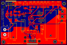
This is much better now, now a bit of optimization-shortening traces and editing 🙂 .
So, this is my last iteration, ready to go?
board is 66x44mm
Attachments
Last edited:
One IV, diskrete, SE, Non-complementary, good for use with tube DAC end and transformer.
This version is for +-12V and 2mAp-p Io without current injection.
Very cool and totally wild 🙂
What is the input impedance of this strange new device?
But seems you can go over 48 Khz input...with that chip; so bye bye all the 98 and the 192 Khz matérials ?!Yes we compared with DIY DAC with PMD100 stand alone mode and PCM63 DACs.
In short with PMD sound was rich, natural, body.
Same HDCD plug in "`blof", no substance no body 🙁
disappointment...
My understanding is 55kHz is the limit at the input, so in real world 48kHz format would be the highest (= what DAT used to have back then, which was the max anyway in the 90s)
@miro1360 on Aliexpress there are a lot of AD1864N-K, they are a little cheaper than AD1865 but it is a very good year, 92. How much work is it to modify the PCB from AD1865 to AD1864?
Does anyone have experience with the 1864 in general, how does it sound compared to the 1865. As far as I can see, everything is the same except that it requires another -5V on the digital part.
Does anyone have experience with the 1864 in general, how does it sound compared to the 1865. As far as I can see, everything is the same except that it requires another -5V on the digital part.
And yes, there is another difference. AD1864 can be powered with +-5 to +-12V both digital and analog part.
HiVery cool and totally wild 🙂
What is the input impedance of this strange new device?
It depends on devices are used.
But generally is about 4 to 6 ohms.
I think I wrote on the schematic...
with few parts are went trough the spice...
.
Somehow slight better with JFET vs MOSFET
input impedance is more uniform in extended BW
.
I made jefet and simplified versions, because @Lazy Cat circuits are for high power usage,
and for IV purposes currents are low...
Last edited:
Thanks. If it's not difficult for you, if you don't hate drawing PCBs, maybe we'll try that, along with everything else. 😁
https://vi.aliexpress.com/item/1005008346148305.html
https://vi.aliexpress.com/item/1005008351067535.html
https://vi.aliexpress.com/item/1005005967364613.html
Because of the shift registers, the digital part would be powered with +-5V and the analog part with +-12V (optional +-5).
https://vi.aliexpress.com/item/1005008346148305.html
https://vi.aliexpress.com/item/1005008351067535.html
https://vi.aliexpress.com/item/1005005967364613.html
Because of the shift registers, the digital part would be powered with +-5V and the analog part with +-12V (optional +-5).
@Zoran,
I try to understand the shematic. Is it a passive I/V with amp after in voltage domain made by the MostFET (M2 or M3) ?
I wonder if AD1862, PCM63, have a maximum advised I/V resistor to stay in the spec sheet like the 7 ohms of the TDA1541A for illustration. Or does it not matter in such circuits ?
I try to understand the shematic. Is it a passive I/V with amp after in voltage domain made by the MostFET (M2 or M3) ?
I wonder if AD1862, PCM63, have a maximum advised I/V resistor to stay in the spec sheet like the 7 ohms of the TDA1541A for illustration. Or does it not matter in such circuits ?
It is not passive IV it is an active transimpedance circuit. The DAC Iout is not loaded with Riv...@Zoran,
I try to understand the shematic. Is it a passive I/V with amp after in voltage domain made by the MostFET (M2 or M3) ?
I wonder if AD1862, PCM63, have a maximum advised I/V resistor to stay in the spec sheet like the 7 ohms of the TDA1541A for illustration. Or does it not matter in such circuits ?
The circuit can be used vor all current output dacs. With adjusted current for DACs that need current injection (TDA1540, TDA1541A) or dac that alredy has -IoDC (PCM1794). And all other Current output dacs as PCM56, PCM63, AD series etc.
HELP!
I built the AD1862 version without issue but I can't seem to figure out this TDA1541A - faint sound, lots of static.
I have confirmed the chip is good in another DIY DAC as well as the COAX to I2S conversion. All input voltages are correct and tried another set of LM6171 opamps.
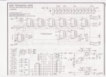
I'm not sure what the different shift registers should be showing.
Can you all point me in a direction to focus on. Thanks!
I built the AD1862 version without issue but I can't seem to figure out this TDA1541A - faint sound, lots of static.
I have confirmed the chip is good in another DIY DAC as well as the COAX to I2S conversion. All input voltages are correct and tried another set of LM6171 opamps.
I'm not sure what the different shift registers should be showing.
Can you all point me in a direction to focus on. Thanks!
Attachments


Thanks Zoran, so indeed the value of Ri/v is not limited as if it was passive.
I wonder what is the trade off of the R value after such circuitry (disto, linéarité...).there are bigger power mosfet but I don't know if it can be better in order to lowish the i/V.
I assume first the goal is to make the input résistance the lower to zéro.
Have you ever measured the output capacitance of the ad182, please ?
Btw yesterday I looked at the datasheet of the NLA OPA660, there is the simplifier internal shematic. Input résistance of the emitter is not writted. But the successor op861 has here 7 to 12R on its datasheet. 😀
- Home
- Source & Line
- Digital Line Level
- DAC AD1862: Almost THT, I2S input, NOS, R-2R