I need to revisit using @Zen Mod's Pass D1 I/V. I had a bad hum and could not set the offset to zero.
How do you wire it for using it with single output DAC vs symetric output it was made for, please ?
Should the - R and -L inputs left floated or to ground or ?
@zenmod : is there better than the IRFP today or do you advice to cope to the shematic (bacause the values of the parts, etc), please ?
Thanks

Yes, there are some other errors, pin 4 of the op amp is on + and pin 7 on -, that needs to be reversed. C5 can also be TH when you already have them on the PCB. Try to make your PCB to have three reference points, ground, + and floating ground that you get through resistor R3.Hey @grunf, did you look at my last iteration of the tube reg?
This is the regulator I have in my DAC, +/-5V but with a slightly higher max current of 500mA because it powers eight PCM1702s. It is necessary to replace the op amp to be bipolar in this case, ADA4897 is the best I have tried, also some resistor corrections need to be made and that's it, everything else remains the same. What would be the input voltage of the regulator and what is the load current?I saw the shunt regulator schematic shared by Vunce in post 7343, that gives an output of +/- 12V. Is it possible to tune that design to get the value +/- 5V output?
Attachments
OK, what do you mean with reference points here? 3 copper areas for gnd, hv and virtual gnd?Yes, there are some other errors, pin 4 of the op amp is on + and pin 7 on -, that needs to be reversed. C5 can also be TH when you already have them on the PCB. Try to make your PCB to have three reference points, ground, + and floating ground that you get through resistor R3.
As Walt Jung's document states that the regulator must be feed 8V above output voltage I was thinking to use a symmetrical 15V supply to get 5V at regulator's output (I also have several 12V power supplys but I supose that will not be suitable). Current will be below 100ma, more in 50ma region, but if you are squeezing 500ma out of yours... we never know what toys in the future we may want to play with🙂What would be the input voltage of the regulator and what is the load current?
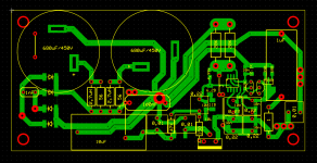
Well, one layer is enough for this regulator, I thought you should separate the decoupling to the ground and to the floating ground from + , and let + to have shorter traces. Unfortunately I can't find the sketches of my last PCB but I found one from another never finished project, it's the same schematic so maybe you'll get an idea. That was supposed to be the HV regulator for my DAC with PCM1794.OK, what do you mean with reference points here? 3 copper areas for gnd, hv and virtual gnd?
Attachments
If you only need 50mA then the voltage drop with the correct selection of depletion mosfet can be only 4 to 5V. Then everything can be done in SMD without the need for additional heatsinks. The maximum I got with this design is 120mA precisely because of that small voltage drop and less dissipation. For larger voltage drops you need a heatsink but that larger voltage drop also increases the PSRR of the regulator itself. For 500mA both depletion mosfets must be in TO220 and then the voltage drop must be even greater than the 8V recommended by Walt Jung, in my case it is 14V and exactly divided in half for each mosfet.As Walt Jung's document states that the regulator must be feed 8V above output voltage I was thinking to use a symmetrical 15V supply to get 5V at regulator's output (I also have several 12V power supplys but I supose that will not be suitable). Current will be below 100ma, more in 50ma region, but if you are squeezing 500ma out of yours... we never know what toys in the future we may want to play with🙂
500mA is also the limit for the IXTP08N50D2.
One important thing about shunt regulators is that they are designed for a specific current and voltage, so I wouldn't recommend using too much excess current because it will unnecessarily load the regulator and the shunt transistor. At the same time, the dissipation is higher and there are no significant benefits in terms of performance.
View attachment 1358644
Does anybody in the US have a spare one of these boards? TPA6120 I/V
From this post - https://www.diyaudio.com/community/...st-tht-i2s-input-nos-r-2r.354078/post-7795053

Does anybody in the US have a spare one of these boards? TPA6120 I/V
From this post - https://www.diyaudio.com/community/...st-tht-i2s-input-nos-r-2r.354078/post-7795053
I had a look at the datasheet, here, and there are several pinouts according to the ada4610 version, but I do not get + on 4 and - on 7 anywhere, please correct me.Yes, there are some other errors, pin 4 of the op amp is on + and pin 7 on -, that needs to be reversed. C5 can also be TH when you already have them on the PCB. Try to make your PCB to have three reference points, ground, + and floating ground that you get through resistor R3.
Well, one layer is enough for this regulator, I thought you should separate the decoupling to the ground and to the floating ground from + , and let + to have shorter traces. Unfortunately I can't find the sketches of my last PCB but I found one from another never finished project, it's the same schematic so maybe you'll get an idea. That was supposed to be the HV regulator for my DAC with PCM1794.
here I don't get your message, ok, can do a star ground, give HV shorter traces, but what do you mean with "separate the decoupling from + to the floating ground, if the big resistor goes to main gnd ?
Grunf said that this need to be reversed, if i understand him correctly.I do not get + on 4 and - on 7
so ok, hope this worksWell, one layer is enough for this regulator, I thought you should separate the decoupling to the ground and to the floating ground from + , and let + to have shorter traces. Unfortunately I can't find the sketches of my last PCB but I found one from another never finished project, it's the same schematic so maybe you'll get an idea. That was supposed to be the HV regulator for my DAC with PCM1794.
isolated the main ground and B+ regions, keeping out the virtual ground.
Attachments

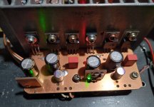
So far with AD1862 I've tested following OP-amps.
ADA4625
OPA1655
Bursson V6 classic
LME49710
AD797
For me best sounding is AD797 even better than Burson. OPA1655 for such price is also very very good. Let's to see how will sound AD811
Someone in this thrrad inputed about his conf with AD797, it is in miro1360 blogspot links.
Did you setuped yours according the datasheet? :
Attachments
For AD797 in any case, 47pF from pin 8 to Out is must. Also Decoupling as stated in datasheet is impotrtant. Off set null is option but if i remember well, it is not an issue, anyway it should be existing as option.
Sound is very good and unique. Nor as usual OP amp sound.
.
I was maybe more satisfied with AD8066, but this amp is in class A and cant stand alone without heatsink noted PS values. So I decresed to +-8V. After that was more than good... Consider this AD8066 seriously.
Sound is very good and unique. Nor as usual OP amp sound.
.
I was maybe more satisfied with AD8066, but this amp is in class A and cant stand alone without heatsink noted PS values. So I decresed to +-8V. After that was more than good... Consider this AD8066 seriously.
25y after testing some Audio Notes 3.X Signature, "thanks" to this thread and all the tempting hype, I am again intringued by R2R DACs.
So I need to find out... hence some question to those with first hand experience.
Has someone here ever tried an Ares 12th Anniversary against one of these AD1862 builds?
If so, would you please be kind to share :
I understand comparisons are not always easy, and also that the DIY journey is not just about sound of course!
I understand also that my ears aren't yours and that builds here have very different specs and hence different sonic signatures.
This is just to have a rough idea on "where we are"...
Background: as I was quite fascinated by all this thread but without having access to any of these builds, I borrowed my neighbour's Ares 12th Anniversary. I believe I have now a very precise idea TO MY EARS and in MY very own system of its strengths and weaknesses vs my very own DAC... and more reasonably, talking modern cheap but acceptably performing offerings, a SU-9, a D70S and an Eversolo Z8.
What I would need now are hints on the potential sound improvement of these interesting AD1862 builds vs the Ares 12 to assess if what I heard through the Ares is say "generaly quite representative of what R2Rs proposed in this thread can achieve"... or not at all by miles.
PM also welcome if too sensitive...
Many thanks guys!
Claude
So I need to find out... hence some question to those with first hand experience.
Has someone here ever tried an Ares 12th Anniversary against one of these AD1862 builds?
If so, would you please be kind to share :
- what were your settings on the Ares (OS filter used... or NOS mode, all this making the Ares sounding quite different to my ears)
- what were your comparative findings "Ares 12 vs your AD1862 DAC"
I understand comparisons are not always easy, and also that the DIY journey is not just about sound of course!
I understand also that my ears aren't yours and that builds here have very different specs and hence different sonic signatures.
This is just to have a rough idea on "where we are"...
Background: as I was quite fascinated by all this thread but without having access to any of these builds, I borrowed my neighbour's Ares 12th Anniversary. I believe I have now a very precise idea TO MY EARS and in MY very own system of its strengths and weaknesses vs my very own DAC... and more reasonably, talking modern cheap but acceptably performing offerings, a SU-9, a D70S and an Eversolo Z8.
What I would need now are hints on the potential sound improvement of these interesting AD1862 builds vs the Ares 12 to assess if what I heard through the Ares is say "generaly quite representative of what R2Rs proposed in this thread can achieve"... or not at all by miles.
PM also welcome if too sensitive...
Many thanks guys!
Claude
I love your regulator and its small footprint. For me, smd is the way to goThen everything can be done in SMD without the need for additional heatsinks
One important thing about shunt regulators is that they are designed for a specific current and voltage
What I'm not ble to realize in the circuit I've mentioned is if is viable to tune the opamp inputs to make the regulator act adjusting output to 5V instead of 12V. Can you shed some light on this please
For AD797 in any case, 47pF from pin 8 to Out is must. Also Decoupling as stated in datasheet is impotrtant. Off set null is option but if i remember well, it is not an issue, anyway it should be existing as option.
Sound is very good and unique. Nor as usual OP amp sound.
.
I was maybe more satisfied with AD8066, but this amp is in class A and cant stand alone without heatsink noted PS values. So I decresed to +-8V. After that was more than good... Consider this AD8066 seriously.
And AD8065,, its single channel iteration.
Do you remember the resistance and capacitance values you used inthe feed back loop, please ?
Its input resistance is monstrously high but the AoL is high... did you model its impedance bandwith ?
I remember JosephK simed some and the op828, AD4899-1, op856, were better. Of course the op1611 (but a lot of people noticed its thin sound as well as the LM4562. Perhap due to very clean/quiet midrange, that gives less bass subjectivly noticed some ????). The op828 is often reffered by TI for the brandnew op627...
Did you noticed a subjective lack of bass or at least tigther/more damped ? As you tried th AD711, I suspect this one to be fuller cause CFA (but also noisier in the audio range because of that), some lover of tubes may prefer the CFA perhaps or at least if not lovers,, a confort im mid area but the ad8065 for sure will be less noisy and cleaner I believe... Certainly two different way tolisten to the music !
Last edited:
- Home
- Source & Line
- Digital Line Level
- DAC AD1862: Almost THT, I2S input, NOS, R-2R