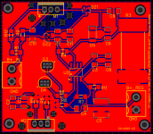
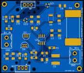
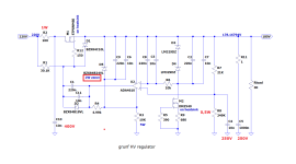
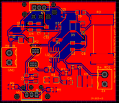
Here comes v2, HV traces are thicker, spacing is wider, added holes around the MOS, it is only 1cm per side wider.So fellows, as a new year's greeting, a board for @grunf 's HV regulator, as presented in one of his answers in the thread.
All SMD, measuring just 41x43mm (heatsinks excluded), is a nice add on between the PSU and the CCS, yes, goes between my two previous boards, in the b+ section of course.
- IT IS NOT TESTED YET
- in the BOM I compiled additional quantities of components for my purposes, so if you want to build only one or two, please amend the quantities.
- do no forget heatsinks!
- start soldering ADA4610 first, then the SMD zeners DZ1 and DZ2, resistors, capacitors, the few THT components, MOSFETs, the big SMD 5W resistor, terminal blocks.
- for 2W zener D5, look for SMZ24 2W.
- regulator LM329DZ is EoL, though quite easy to be found around (not China). There are some equivalent, but for DC stability and noise figure we prefer this one.
Plug 1 side of the B+ of my psu board to the input terminal, with 220VDC in you should get 180VDC ripple free at the output.
I would then connect the output to the 2 b+ tube board inlets, I know that grunf comes to correct me saying "use two reg boards, one for each triode of the 6n23p", but i guess that currentwise it should work 😀
You are of course free to test with 2 boards, one for each side.
This boards stems from my curiosity to test a b+ regulated supply in tubes, since I've never done this before, and since if get a wonder like in the AD811 board, well, i will revise all my ideas about super ultra mega iper refined supplies (ok, this is perhaps not super ultra mega iper, but a big step beyond my basic 5$ board).
Questions, doubts, opinions, corrections (especially from the author) are more than welcome!
Attached are original schematic, my schematic, BOM and Gerber.
Happy new year guys ! 😛
Let's wait for @grunf 's approbation 😀
Attachments

I do not have these specific caps. I will try to dig out more caps on the weekend and will post.
- Cornell Dubilier CD940
- Kemet C4AQ (or similar, small and non expensive...)
Try to measure Wima MKP10 - it's a standard cap in use everywhere.
Some good caps should be Vishay MKP1840 ( think Morgan Jones used them in the last edition of his book for coupling purposes ) & Vishay 1839 axials.
Regards, Krca
Some good caps should be Vishay MKP1840 ( think Morgan Jones used them in the last edition of his book for coupling purposes ) & Vishay 1839 axials.
Regards, Krca
Frankly if we take care to make a DAC and use a MKP10 as DC blocking, we certainly missed something. It is not that is a bad cap, but it is not good enough but if you want to make cheap.Try to measure Wima MKP10 - it's a standard cap in use everywhere.
Some good caps should be Vishay MKP1840 ( think Morgan Jones used them in the last edition of his book for coupling purposes ) & Vishay 1839 axials.
Regards, Krca
I disagree as here we talk about blocking DC cap after a tube stage. I tried. (if you mind with another one circuitry than mine) and also loudspeakers.
I am talking of serie cap if you took the time to read the thread few posts above we talked about the MKP10 in serie an output DAC stage.
In my book it is really "not good enough".
I am talking of serie cap if you took the time to read the thread few posts above we talked about the MKP10 in serie an output DAC stage.
In my book it is really "not good enough".
Why?If you build a DAC and the Wima makes it sound "not good enough", something is wrong with the circuit.
There is no way to compare a CMR or a tin foil with MKP10 but if you want to hide some things... (ime).
For the price of a MKP 10 a Panasonic DC link will go further. I didn't tried though the Vishay you linked.
Now one can always play with caps to correct a little a tonal signature. MKP10 is really not good at that, missing a little everywhere in my experience,a little veilled vs some other polypro. Of course there is worse. But it is not really ime a so ggod priced cap in that DC blocking use.
Of course eveything is very circuit dependant etc., but, for whatever it is worth...
Some time ago I did my usual test, that is having a test rig where everything works fine and just add a component on the signal path to see how it would affect the sound. Of course the added component is chosent in terms of specs and (if passive) values in a way that "in theory" it shouldn't affect the response (no noticeable Fc, FET when required etc.). it can easily be switched in and out for direct comparisons. Of course that just gives some hints regarding sonic signature when used in the signal path and for analogic circuits - not PS or digital - but well, it can be helpfull to pick up a limited number of components before finalising a choice.
Long story short, the outstanding transparent components so far are :
The CD 940 caps are not too expensive but of course bulky. Having said that, no cap is best cap, but with CD 940 (once broken-in) I can't here if it is there or not (and I tried hard inclusive on headphones), so not too bad IMHO....
All IME
Have fun
Claude (who used to hate caps and op amps decades ago!)
Some time ago I did my usual test, that is having a test rig where everything works fine and just add a component on the signal path to see how it would affect the sound. Of course the added component is chosent in terms of specs and (if passive) values in a way that "in theory" it shouldn't affect the response (no noticeable Fc, FET when required etc.). it can easily be switched in and out for direct comparisons. Of course that just gives some hints regarding sonic signature when used in the signal path and for analogic circuits - not PS or digital - but well, it can be helpfull to pick up a limited number of components before finalising a choice.
Long story short, the outstanding transparent components so far are :
- CD 940 caps (I love these, they shine where ever I use them)
- OPA 1612 (not saying it is the one I prefer - OPA1656 is very neutral while a tad more "musical to MY ears", but OPA 1612 is as neutral and transparent as it gets when the circuit is suited for it)
The CD 940 caps are not too expensive but of course bulky. Having said that, no cap is best cap, but with CD 940 (once broken-in) I can't here if it is there or not (and I tried hard inclusive on headphones), so not too bad IMHO....
All IME
Have fun
Claude (who used to hate caps and op amps decades ago!)
I'm sitting out the coupling cap discussions because I simply use 0.1uF Russian FT-3 teflons from my ECC40 I/V stage into 100K on the following valve stage. Everything else I've tried sounded worse, and I went through quite a lot of other options. I've used FT-2 and FT-3 for around 20 years now.
I've used FT-2 and FT-3 for around 20 years now.
You have certainly made this known in many, many threads
Being polite i would call these caps an acquired taste
🙂
But seriously, why discuss caps here again? Not enough cap threads elsewhere?
I have to warn about the voltages of some capacitors. Others can be 50V or 63V. Mouser has some SMD 1uF/250V in stock. Put the gate stoppers right next to the gates of the mosfet.Here comes v2, HV traces are thicker, spacing is wider, added holes around the MOS, it is only 1cm per side wider.
Let's wait for @grunf 's approbation 😀
Attachments
Well, over 20 years of using them I'm not surprised that they have come up in a number of posts.You have certainly made this known in many, many threads
Being polite i would call these caps an acquired taste
🙂
But seriously, why discuss caps here again? Not enough cap threads elsewhere?
As you say, teflon coupling caps appeal to some and not to others. I'm a big fan - I find them neutral and very detailed. For me they make other caps sound coloured and veiled. Others like things like PIOs. I haven't spent big money on boutique caps, so when it goes above £50 I leave it to others.
As you know I hang out on the tube forums because that's what I build. I come here for the DAC stuff, but I sometimes add a post or two about tube output stages when they are discussed here. I certainly don't want to get into mainstream tube stuff here, or even capacitors beyond the basics, so I'm with you there.
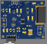
here you go, although couldn't find 400V SMD caps, and as 2W zener in SMD there is only this SMZ24. We give it a go ?I have to warn about the voltages of some capacitors. Others can be 50V or 63V. Mouser has some SMD 1uF/250V in stock. Put the gate stoppers right next to the gates of the mosfet.
Attachments
There are other types; 1SMB5934BT3G, 1SMB5934B-W, 1PGSMB5934,CZRB5359B-HF..... Calculate that this diode will have about 300mW of dissipation, so give it a little more copper surface area.
As for 10nF/400V, you have FCN1913G103J-E3 and SMDTG02100TA00MQ00.
It would be a good idea to put a decoupling capacitor at the regulator input, for example 0.1uF/400V (CB162I0104KBC). You can make the PCB so that the capacitors are TH as well as the power resistor and everything else is SMD.
As for 10nF/400V, you have FCN1913G103J-E3 and SMDTG02100TA00MQ00.
It would be a good idea to put a decoupling capacitor at the regulator input, for example 0.1uF/400V (CB162I0104KBC). You can make the PCB so that the capacitors are TH as well as the power resistor and everything else is SMD.
- Home
- Source & Line
- Digital Line Level
- DAC AD1862: Almost THT, I2S input, NOS, R-2R