i am not sure if it was defective or i killed it .. i made a stupid mistake when i connected the power supply headers the opposite way at first try . +5v to -5v and vice versa . both fuses of the miro v2 power supply blew and then i saw it and put the headers the right way . The other chip seems ok i hear music without any audible noise .Why don't you use it as an active I/V, picture 5.?
Didn't that device accidentally kill that one PCM 1702? 🤔
So it is an active I/V .. i thought it needs an I/V resistor seeing grunf tube circuit 🙄
https://www.diyaudio.com/community/...st-tht-i2s-input-nos-r-2r.354078/post-6971024
Last edited:
Everything is tested without chips. Power supplies are tested with resistors wired for an hour or two at a higher than expected load. The voltages on all chip sockets are checked. Then it's just a matter of inserting the chips.
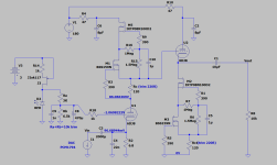
I used a 6S4P for one PCM1702 which has almost four times the gain of the ECC86 and that's the whole problem. The PCC86 has too little gain just like the ECC88 for the current of 1-1.2mA of the PCM1702 or AD1862. It is necessary to choose a tube with a higher gain and then the Riv can go low. Good triodes for IV, in my opinion, are all with a higher amplification factor, such as EC86, 6HM5 and similar. Then the possibilities for playing with Riv with a sufficiently large output voltage open up.i am not sure if it was defective or i killed it .. i made a stupid mistake when i connected the power supply headers the opposite way at first try . +5v to -5v and vice versa . both fuses of the miro v2 power supply blew and then i saw it and put the headers the right way . The other chip seems ok i hear music without any audible noise .
So it is an active I/V .. i thought it needs an I/V resistor seeing grunf tube circuit 🙄
https://www.diyaudio.com/community/...st-tht-i2s-input-nos-r-2r.354078/post-6971024
I was also more satisfied with the sound of the tubes with higher amplification than with, say, the ECC88. For example, ECC88 could be great for PCM1794, which will be my next candidate for a diy DAC (and to solve those 100mV on the cathode 😉 ).
Attachments

If I may, a couple of short questions concerning part selection from my inventory.
1. I have a 50 pack of Vishay 150nf, 63V, 5%, Metallized PET caps. Can I use on the DAC board and the PSU1 in the position of the 100nf caps ? Otherwise, I will have to order some other 100nf caps. The Vishays are the thin grey ones.
2. I have found some Elna Silmic II 47uf/50V caps that I propose to use for C16, C26. I also have the 4.7uf Elna's for C15, C25. OK to use?
I thought I read / saw pics that Nixie used some 47 uf Simics in the positions in question #2, but wanted to check.
Thanks again for the help,
MM
I am considering an E88CC or 6N1P in a Mu Follower configuration for the PCM63 as I have several pairs of those tubes, well matched. The I/V resistor in that case is 50 ohm, and the gain is about 30x for an output of at least 2VRMS. For AD1862 & PCM1702, the I/V resistor in that combination would have to be 100ohm, I don't know if that's too much?ECC88 could be great for PCM1794
I have 3 regulators for +-5v,+-12v for ad1862 chip and +-15v for I/V and each regs have gnd
What is the best way to connect gnd?
What is the best way to connect gnd?
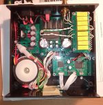
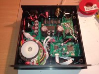
While I was watching the Australian Open with one eye, I built a small DAC with AD1865 N-K with another one. It's not exactly a Miro DAC, it's a Pavouk DAC, but the schematic is similar.
It has only a USB input, I took a Chinese Amanero USB/I2S card with SITIME oscillators, upgraded version. Works flawlessly with original Amanero WIN10 drivers.
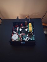
The transformer is custom made 10VA. It has a grounded static shield between the primary and secondary windings and magnetic shielding. Transformer secondaries have snubbers determined by the Quasimodo tester. There is not a trace of hum even if the transformer is very close to PCBs.
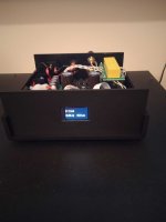
It also has a small Chinese display for sampling rate. It says Welcome when it turns on. 🤣
It has only a USB input, I took a Chinese Amanero USB/I2S card with SITIME oscillators, upgraded version. Works flawlessly with original Amanero WIN10 drivers.
The transformer is custom made 10VA. It has a grounded static shield between the primary and secondary windings and magnetic shielding. Transformer secondaries have snubbers determined by the Quasimodo tester. There is not a trace of hum even if the transformer is very close to PCBs.
It also has a small Chinese display for sampling rate. It says Welcome when it turns on. 🤣
Attachments

I have idea to use Singxer SU-6 instead Jlsound. SU-6 is very very good product and has I2S output MCLK, BCLK, LRCLK, SDATA. Is it possible to connect it to the AD1862?
I just saw note:
J1-J13: is 0R resistor, or a wire jumper for the PSU 1. Use 2R2 or 3R3 resistors for the PSU 2.
I use PSU2 and wire jumpers. What is different between jumpers and resistors?
Also at R10 and R11 I use 100 Ohm. What is different if I put jumper?
J1-J13: is 0R resistor, or a wire jumper for the PSU 1. Use 2R2 or 3R3 resistors for the PSU 2.
I use PSU2 and wire jumpers. What is different between jumpers and resistors?
Also at R10 and R11 I use 100 Ohm. What is different if I put jumper?
I also forgot the R2R. The reason is explained here: https://www.diyaudio.com/community/...s-input-nos-r-2r.354078/page-104#post-6676470
But you can also just put the resistors on the temrinals of the PSU2, as explained here: https://www.diyaudio.com/community/...s-input-nos-r-2r.354078/page-193#post-7008388
That's what I did.
But you can also just put the resistors on the temrinals of the PSU2, as explained here: https://www.diyaudio.com/community/...s-input-nos-r-2r.354078/page-193#post-7008388
That's what I did.
Ok I understand. But what about R10 and R11 on output.
BTW, I successfully modified psu2 in order to get 2x+5v. If someone need, it's very simple.
BTW, I successfully modified psu2 in order to get 2x+5v. If someone need, it's very simple.
Miro explained it here.
I used a lower value, 22r.
I guess if you short it and there is no stability issues, then you are good.
https://www.diyaudio.com/community/...2s-input-nos-r-2r.354078/page-59#post-6447335
I used a lower value, 22r.
I guess if you short it and there is no stability issues, then you are good.
https://www.diyaudio.com/community/...2s-input-nos-r-2r.354078/page-59#post-6447335
It says Ready ... I don't know how I got this wrong above. Mixed up with something else. 😳It says Welcome when it turns on.
Finally used modified PSU2(2x5v) for Jlsound board. Separate for digital and analog. Jlsound spend less than 400mA as it specified but 1963 regulator become very hot. Didn't expect but this regulator require really big hetasink for currents much bellow maximum.
It all writes here in this topic 🙂 We use as big as we can fit. It is an LDO, the get quite hot especially if drop is higher. What V is pure dc you're providing to it?
- Home
- Source & Line
- Digital Line Level
- DAC AD1862: Almost THT, I2S input, NOS, R-2R