That is around 15Vdc. So you are providing that LDO with 10V voltage drop. That will get very hot 🙂
That is certainly too much. That was the case with the @mikorist DAC, it only had one secondary 12VAC 1,5A available for XMOS. I put wire resistors in front to reduce the heating of the regulator. 2x3R9 5W as I recall, one on each AC outlet. The real deal is a 7- 8VAC secondary for XMOS part and another secondary 7-8VAC for the oscillator part.
it doesn't matter what it says on the screen. That dac is going to have a nice new home.🤣While I was watching the Australian Open with one eye, I built a small DAC with AD1865 N-K with another one. It's not exactly a Miro DAC, it's a Pavouk DAC, but the schematic is similar.
It has only a USB input, I took a Chinese Amanero USB/I2S card with SITIME oscillators, upgraded version. Works flawlessly with original Amanero WIN10 drivers.
The transformer is custom made 10VA. It has a grounded static shield between the primary and secondary windings and magnetic shielding. Transformer secondaries have snubbers determined by the Quasimodo tester. There is not a trace of hum even if the transformer is very close to PCBs.
It also has a small Chinese display for sampling rate. It says Welcome when it turns on. 🤣
First post in this thread—I started this DAC years ago at this point—recently reinvigorated since I'm finally annoyed enough that the DAC is the only thing in my system that isn't DIY. Ha!
I built the first version with the shift resistors, but always planned to use the JLSounds board... then I became aware of the more recent version that's more integrated and compact, so, had some made...
Pics here for a configuration/stuffing check—I think I've reviewed everything....I have the v2 PSU (ready to go), and chassis parts sitting here, might have it playing near the weekend.
Thanks!

Those would be 2R2 per the docs here for optimizing Miro's V2 PSU....but please check the rings (I just checked the bag and I certainly metered them before stuffing...but that process hasn't prevented 10K for 10R etc. and more! ;-)—I don't have those ring codes to memory or at hand, and I always seem to forget the system there (I will of course review later when I have a moment). 22R are under the JL board (R1-R3, R12).
EDIT: Couldn't wait, Haha... Red=2, Silver=nothing, Black=0, Red=2, last Red=50ppm. So good?
EDIT: Couldn't wait, Haha... Red=2, Silver=nothing, Black=0, Red=2, last Red=50ppm. So good?
Last edited:
Ah I see now, missed the silver/ gold band difference.
My point was that they should be links, I've read that PSU 2 can need some resistance on the output so all good.
Don't forget R13 by the JLS board dirty side header on the DAC board, how are you going to power the USB board?
Andy
My point was that they should be links, I've read that PSU 2 can need some resistance on the output so all good.
Don't forget R13 by the JLS board dirty side header on the DAC board, how are you going to power the USB board?
Andy
Okay! That's what I was looking for—feedback! Thanks! Will stuff R13—this resistor isn't required on the newest new JL board? I might pick up another for another build (should have bought 2 to start.)
I'll power USB with the v2 PSU 5V @VD—do I have that configured right?
I'll power USB with the v2 PSU 5V @VD—do I have that configured right?
If you want to power both analog and digital part of usb you need to modify psu2. I can show you how to do it.
Educate me. I thought the USB could be powered via USB bus (if available, it is in my case) OR via the 5V rails of v2 PSU attached at VD on DAC PCB.
The choice depends on jumper config (in my case shorting SJ3, for power from VD on DAC PCB via v2 PSU 5V rails)—my JL board version matches the printed USB power instructions on the PCB silk.
What I'm reading above is that USB needs 2 power sources?
The choice depends on jumper config (in my case shorting SJ3, for power from VD on DAC PCB via v2 PSU 5V rails)—my JL board version matches the printed USB power instructions on the PCB silk.
What I'm reading above is that USB needs 2 power sources?
Yes, for your version of the JLSounds VIII board, R13 is required.Okay! That's what I was looking for—feedback! Thanks! Will stuff R13—this resistor isn't required on the newest new JL board? I might pick up another for another build (should have bought 2 to start.)
I'll power USB with the v2 PSU 5V @VD—do I have that configured right?
For the newer board JLSounds VIII FIO board, you skip R13.
The USB 'dirty side' can be powered by your USB Bus.Educate me. I thought the USB could be powered via USB bus (if available, it is in my case) OR via the 5V rails of v2 PSU attached at VD on DAC PCB.
The choice depends on jumper config (in my case shorting SJ3, for power from VD on DAC PCB via v2 PSU 5V rails)—my JL board version matches the printed USB power instructions on the PCB silk.
1. SJ1 and SJ2 on your DAC board is left open.
2. The power path under the JLSounds board is left uncut.
So you have done the above correctly. The USB section of the JLSounds board will be powered by your USB source.
You installed SJ3 zero ohm resistor and J9 resistor. The oscillator + reclock section will then by powered by the +5VD rail from your DAC board.
So basically, the USB and oscillator and relock are now isolated from each other.
J4 on JLSounds board is shorted.....
You are good to go now.

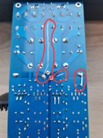
If you need to power separately digital/analog part of Jlsound, PSU2 can be modified according to this picture. With this modification you will get 2x +5v from PSU2.
Red is bottom pcb cut. Blue is top pcb cut. Green is short connection. You should populate only +5V elements as you can see on the picture.
3. Using two external power supplies. One must cut external power supply jumper
located on the bottom side of the board, then provide external power supply for
USB side (400mA; 4.0V to 5.3V) on H1.1 and H1.2, provide external power
supply to H3.17 and H3.19 (100mA, 4.5V to 5.3V).
Attachments
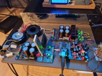
That's the worst of all. 🤣Now to make a chassis…
Will be listening this weekend I'm sure...Will probably put a steel divider in and certainly can the toroid.
Any opamp recos? Easy now—I know this could be loaded 🙄—the Bursons are just there since they were free and I don't have any other place to put them...and wanted to make sure they'd fit the case. Made the case to match the width of my preamp—room for expansions or later projects.

Any opamp recos? Easy now—I know this could be loaded 🙄—the Bursons are just there since they were free and I don't have any other place to put them...and wanted to make sure they'd fit the case. Made the case to match the width of my preamp—room for expansions or later projects.
Go with an r core and a divider
Send a pic when it’s wired
Try an lm6171
I’ve got a very similar setup, stayed with the Burson Vivid. Didn’t listen enough to really appreciate the differences
Send a pic when it’s wired
Try an lm6171
I’ve got a very similar setup, stayed with the Burson Vivid. Didn’t listen enough to really appreciate the differences
Last edited:
Do you have a part number for an R core tranny? I've never used one personally, the toroid I had on the shelf and it will work...
- Home
- Source & Line
- Digital Line Level
- DAC AD1862: Almost THT, I2S input, NOS, R-2R