Happy holidays all.
Does anyone with both Miro1862 and 1541a have a subjective opinion on them in comparison to each other?
Does anyone with both Miro1862 and 1541a have a subjective opinion on them in comparison to each other?
Agreed, PCM63 is very, very good. It’s like splitting hairs for me - they’re all very good. I’d be happy with 1862, PCM63, or tda1541a as my only Dac. That said, I’ve been listening to the tda1541a more lately. Of course, that could be because it’s the newest of the three 🙂

I do not have pcm63, but I have Miro''s AD1862 and Tda1541. I cannot resist the TDA1541 midrange magic. Argghh ... I have been resisting the PCM63...Agreed, PCM63 is very, very good. It’s like splitting hairs for me - they’re all very good. I’d be happy with 1862, PCM63, or tda1541a as my only Dac. That said, I’ve been listening to the tda1541a more lately. Of course, that could be because it’s the newest of the three 🙂
I'm just kidding. As for me, I'm slowly building a universal power supply (+-5V digital part, +-5V analog part, +-12V analog part) and two DAC PCBs, one with an AD1865 and one with a PCM63 so I'll try both with that power supply. I have JLS I2S over USB board and AK4113 receiver board (SPDIF/TOSLINK/I2S inputs, I2S output) and power supply for all that already done and tested. I'm also planning a slightly different I/V stage to add externally to try. I collected almost all the parts, just to find the time.
I have had a Miro AD1862 for quite a while now and really enjoy it. I need to try some different PSU and digital front end options. But in the meantime I won an old Philips CD Player with 1541A inside. Assuming I can desolder the thing successfully I will like to build. Miro DAC with it!
I had been using a good soldering station and braid to desolder parts. I bought a Hanko FR-301 and it is WAY better. I desoldered a 28-pin chip and it fell out, that good.
Thanks for the advice. Yes I tend to look at the internal block diagram to make sure I'm not concentrating heat on pins that mate together inside. I am an iron and braid jockey for now but will look into the Hakko
Today I played with TDA1540 setup, but mine input logic on this schematic is not "perfect" because I still hear a few very silent digital glitches in the background (the full stop-clock is not included here). If this worked, the number of chips would be only 7 pcs, which is nice. If I include the full stop-clock with CPLD, glitches are gone. I will probably not continue with the improvement of this schematic, and TDA1540 will most likely end up with the cheapest CPLD board and programmer you can buy from aliexpress, together maybe 10€ 🤣
Attachments
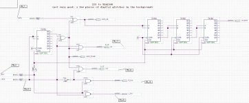
ok, i can have a breather and take a break........ 🤣 🤣Today I played with TDA1540 setup, but mine input logic on this schematic is not "perfect" because I still hear a few very silent digital glitches in the background (the full stop-clock is not included here). If this worked, the number of chips would be only 7 pcs, which is nice. If I include the full stop-clock with CPLD, glitches are gone. I will probably not continue with the improvement of this schematic, and TDA1540 will most likely end up with the cheapest CPLD board and programmer you can buy from aliexpress, together maybe 10€ 🤣
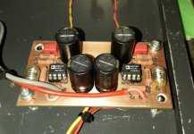
Another PM 63 DAC lives. I’m using it with AD797 opamps. I did connect ZMod’s D1 I/V but was getting a bad hum through it. I need to work on it.
Sounds good. Thanks miro for another great DAC.
Sounds good. Thanks miro for another great DAC.
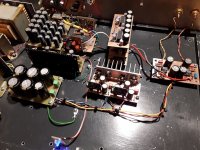
Guys, two days ago I finally turn on the I/V stage with AD811 in my DAC with six PCM1702.
There is no buffer in the output because the AD811 can give 100mA at its output, which means directly to the amplifier without any capacitors.
The regulator is an improved version of Walt Jung's shunt, the voltage on output is +/-10V just enough that the AD811 does not need heat sinks.
The sound is excellent and it seems to me that it is still better than the tubes, so it remains in my DAC for now. There is no need to compare it with classic op-amps, although I will try them too😉
When the New Year's madness is over, I will open a separate topic about the AD811 I/V stage.
And Happy New Year 🎆
Attachments
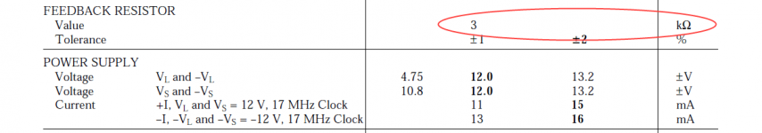
It has orange skin surface, so that is a good sign it is original 🙂 Fakes are most of the time smoothed out to remove previous writings and imprint new. You can also measure it's feedback resistor, but i don't see the value in datasheet so someone that has that chip here, can tell you.
You can also measure it's feedback resistor, but i don't see the value in datasheet
Attachments
A curious question. Is there any other dac chips that will work in a circuit designed for AD1862?
- Home
- Source & Line
- Digital Line Level
- DAC AD1862: Almost THT, I2S input, NOS, R-2R