I experienced 2 capacitor explosions. One small electrolytic flew over my head due to the reversed polarity (from that moment I started wearing safety glasses) - it is really like projectile ... and the second explosion was THT tantalum (the yellow thing in ceramic package), not sure why it happened because it worked for a few months - it was like a grenade with shrapnels 😎
Always have great respect when diagnosing or testing something. Rochester does have the original AD1862, but doesn't offer spare eye
This "hot projectile" can fly quite fast, slow mo guys measured 60 m/s, it can do a serious injury to the eye:
Funny is that a large capacitor with the weakening cross on top is most likely safer than a tiny one without cross 
Always have great respect when diagnosing or testing something. Rochester does have the original AD1862, but doesn't offer spare eye
This "hot projectile" can fly quite fast, slow mo guys measured 60 m/s, it can do a serious injury to the eye:

damit some dacs not only make you deaf, they make you blind too ! Terrible....
Hey guys,
I made some measurements on the AD1862 DAC's outputs without installed chips and oamps.
I made some measurements on the AD1862 DAC's outputs without installed chips and oamps.
- Impedance when it's turned off.
It shows 2MOhm 🤔

Another channel shows 4MOhm
- Impedance when it turned on.
It shows 0L.

Another channel shows 100KOhm
- Voltage when it turned on.
it was showing around 4V and going down slowly.

Another channel shows around 500mV.
This is quite strange, right?
Do you guys have approximate correct values for DAC the outputs?
Where did you buy ldo's from? Did you check all the values of passive components? Check solder joints as well.
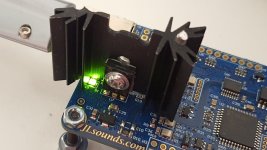
Btw, if you use jlspunds board, my advice is to change the heatsink on the regulator (xmos supply). It is piping hot even with lower supplied voltage (i supply it with 4.6V). It is lukewarm to the touch now, while it was fingerprint erasing hot with default heatsink.
Btw, if you use jlspunds board, my advice is to change the heatsink on the regulator (xmos supply). It is piping hot even with lower supplied voltage (i supply it with 4.6V). It is lukewarm to the touch now, while it was fingerprint erasing hot with default heatsink.
Attachments
how do you mount the heatsink? heatsink glue?Where did you buy ldo's from? Did you check all the values of passive components? Check solder joints as well.
Btw, if you use jlspunds board, my advice is to change the heatsink on the regulator (xmos supply). It is piping hot even with lower supplied voltage (i supply it with 4.6V). It is lukewarm to the touch now, while it was fingerprint erasing hot with default heatsink.
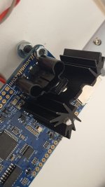
No, regulator has a hole, so i used bolt and a nut as you can see from the picture. Original is slip on, and it has no paste either. I used thermal paste.
i see. i thought i saw the mounting hole on the heatsink is above the tab of the regulator , hence i assumed is not screwed on. Thanks for the tip. I have this board on the way to me.No, regulator has a hole, so i used bolt and a nut as you can see from the picture. Original is slip on, and it has no paste either. I used thermal paste.
I agree that the regulator does indeed, get hot with the supplied heatsink, but I surely would not use a heatsink of that type on this application. There’s no way to securely mount it to the pcb and could lead to shorts if it was bent and touched surrounding components.
hmmm, maybe i will desolder and mount it under the board, mounted to the chassis base. any info on this transistor?I agree that the regulator does indeed, get hot with the supplied heatsink, but I surely would not use a heatsink of that type on this application. There’s no way to securely mount it to the pcb and could lead to shorts if it was bent and touched surrounding components.
Yeah those bigger heatsinks usually have a couple differently spaced hokes. You can use a bit smaller heatsink though, factory one is really bad.
@Vunce yeah, it needs isolator below. I'll be mounting different one when i pack it in box. Nixie will use a smaller to220 one, and if it does the job, i'll mount the ones i mounted on psu ldo's, 17c/w.
@Vunce yeah, it needs isolator below. I'll be mounting different one when i pack it in box. Nixie will use a smaller to220 one, and if it does the job, i'll mount the ones i mounted on psu ldo's, 17c/w.
Those are from Mouser. And PSU voltage is correct. Do you think it can drop down because one of the ldo's is damaged?Where did you buy ldo's from?
I'm building the analog part emulation in LTspice to get reference values on outputs to understand which output channel is actually incorrect.
http://www.kelco.rs/katalog/detalji.php?ID=9675
I ordered these from a local shop, I think they are around 20k/W. Before that, I reduced the heating by putting a 1N4001 diode on the output of the +5V regulator, the voltage drop on the diode is almost 1V at 400mA (dissipation is 400mW on that diode). So now the XMOS is powered with about +4V, which is not a problem because that regulator is for 3.3V and there is another one behind it for 1V. Now it is hot but not too hot as before.
I ordered these from a local shop, I think they are around 20k/W. Before that, I reduced the heating by putting a 1N4001 diode on the output of the +5V regulator, the voltage drop on the diode is almost 1V at 400mA (dissipation is 400mW on that diode). So now the XMOS is powered with about +4V, which is not a problem because that regulator is for 3.3V and there is another one behind it for 1V. Now it is hot but not too hot as before.
I have muses03 and new muses05 now.Hey guys,
have you tried Sparkos or Muses02 oamps with the DAC?
Did you hear any improvements?
Does it worth to upgrade to one of these regarding the price?
Muses03 was my favourite but muses05 surpassed.
I don't have sparkos.
ok i got my board. It is a BD139.hmmm, maybe i will desolder and mount it under the board, mounted to the chassis base. any info on this transistor?
I feel so stupid, I thought it was some kind of voltage regulator, not a single transistor. It is probably the extension of the SMD regulator due to higher dissipation. 😵
It must be pushed to the limit since it heats as much as it does. BD139 is higher dissipation version of BCP56, and now i see why it isn't all smd.
The JLSounds I2SoverUSB sounds fantastic with Miro TDA1541 and AD1862. But yes, the BD139 gets too hot for comfort. I will try it with 3.9V, which is specified as the minimum for operation.
- Home
- Source & Line
- Digital Line Level
- DAC AD1862: Almost THT, I2S input, NOS, R-2R