I didn't think about compromises when making audio for myself.@mikorist , I am curious also because also the layout with the registers ask others trade offs...than also can lowish the rendue...trade offs trade offs...
I don't have a boss above my head. It cost me $900 in parts for this DAC without the box... 😬
Last edited:
You have in the context of this thread cause you use third party Vader Black Star pcb labyrinth layout... Do you feel the path till the reactor my very young padawan ? 🤪🤣
I am done with this topic. I am retiring. 🤣You have in the context of this thread cause you use third party Vader Black Star pcb labyrinth layout... Do you feel the path my very young padawan ? 🤪🤣

LRCK (and BCK for PCM63 too) is driven directly from I2S, so the sound should be equal with shift registers or without 😉curiousity pushs me to see more on the manual of JLsound I2Sover usb. Found the board is also able to provide dataL and dataR directly to PCM63. If do so, can it directly skip the shift registers and result to sound more beautiful?
so a guess
I tested AD1862 with shift registers, without directly on jlsounds and diyinhk usb-i2s, and shift registers with PCM2706 ... no audible difference for me.
But delta-sigma DACs have audible difference between jlsounds or diyinhk and PCM2706.
But delta-sigma DACs have audible difference between jlsounds or diyinhk and PCM2706.
Not true. The shifters will have no effect on the sound provided the circuit is designed correctly. In your case, the circuit is clearly broken. That should have been obvious to any one who saw the schematic and knew how DACs operate. Of course, this is diyAudio where no one looks at a datasheet except to copy the pin-out diagram.And the sound of the PCM63 depends entirely on the shifters.
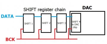
The problem is, at the rising edge of BCK the DAC latches the next data bit and shifts it into the sample register. At the same time, the rising edge of BCK tells the I2C shifter to move the next bit to the input of the DAC chip. Well, which bit is the DAC supposed to use. The bit that was in its input the moment BCK was asserted or the new data bit from the I2S shifter after BCK was asserted. Or maybe a garbled mixture of the two. Simply put, the I2S shifter is updating the sample bit at the very moment the DAC is trying to read it. This error is repeated in nearly every I2S circuit I have seen in this forum! Whether or not it induces audible errors depends on the circuit timing details and the hearing ability of the listener.
I called attention to this problem in my last post here but Miro blew me off. But, what do I know? I'm a software guy and all of you are hardware experts. The forum cognoscenti have told me my contributions are not useful and, although I read a lot of datasheets, I don't know how things work in the real world. OK, I'll shut up let you experts do things your way. It's just that after seeing the same stupid mistakes repeated over and over I can no longer hold my tongue.
@Tam Lin I know what you want to say. These shift registers are tricky and they messed my head many times.
Consider DAC input as the next shift register. So if you connect DACs shift register on the chain, what will happen? 🤔
If the first three registers worked, why the fourth should be broken?
Consider DAC input as the next shift register. So if you connect DACs shift register on the chain, what will happen? 🤔
If the first three registers worked, why the fourth should be broken?
Attachments
Last edited:
beautiful.View attachment 1075277
I'm done... 🤓
Thanks to everyone for everything - especially @miro1360 - without him this would not be possible...😎
It works great. In fact, nothing in the world plays this well.@Tam Lin I know what you want to say. These shift registers are tricky and they messed my head many times.
Consider DAC input as the next shift register. So if you connect DACs shift register on the chain, what will happen? 🤔
If the first three registers worked, why the fourth should be broken?
Here, transients in the signal do not have a limiting process. Reaction time are in nanoseconds.There is no unnatural rise and fall of the level of a certain sound - the level of background noise... because there is no filter... And you can hear it.. I have the impression that the songs are spinning at the speed of light - everything sounds live and freshly broadcast on the air... as if it is not digital - but some perfectly adjusted analog tuner set to capture songs from the PC
Others on the forum have similar impressions. Maybe we are all collectively deaf. But that's it.
Others on the forum have similar impressions. Maybe we are all collectively deaf. But that's it.
Last edited:
I am a softer guy also for more than 35 years. But who cares I've been playing with shifters and the DIN modules since Commodore 64.🤣I'm a software guy and all of you are hardware experts.
I feel a strong need to cuddle this Mikorist DAC for a while and compare it to my DDDAC. It depends on the results whether the DDDAC will remain in my possession, or perhaps the Miro PCM63 will be made.
Next week 😉I feel a strong need to cuddle this Mikorist DAC for a while and compare it to my DDDAC. It depends on the results whether the DDDAC will remain in my possession, or perhaps the Miro PCM63 will be made.
Many of the favored NOS DAC chips have setup and hold times of 10ns or more. Many of the favored shift registers have propagation delays of 5ns or less. The two don’t work together because you end up with the input to the DAC chip changing during the DAC’s hold time. In the extreme you have a PCM1702 with a 15ns hold time and an AHCT164 with a typical prop delay of 3.4ns.@Tam Lin I know what you want to say. These shift registers are tricky and they messed my head many times.
Consider DAC input as the next shift register. So if you connect DACs shift register on the chain, what will happen? 🤔
If the first three registers worked, why the fourth should be broken?
You may ask, why use AHCT when HCT will do the job? For most diyAudiophiles faster is always better and there are many applications where HC logic is too slow. It's best to avoid I2S and shift registers, altogether.
May I ask which method the USB board is using for converting I2S to PMC signal? FIFO?Many of the favored NOS DAC chips have setup and hold times of 10ns or more. Many of the favored shift registers have propagation delays of 5ns or less. The two don’t work together because you end up with the input to the DAC chip changing during the DAC’s hold time. In the extreme you have a PCM1702 with a 15ns hold time and an AHCT164 with a typical prop delay of 3.4ns.
You may ask, why use AHCT when HCT will do the job? For most diyAudiophiles faster is always better and there are many applications where HC logic is too slow. It's best to avoid I2S and shift registers, altogether.
Thanks
@Tam Lin If we use shift register which propagation delay is longer as hold time in DAC, then everything will be fine? The HCT meets this requirement 🙂 ... AHCT was also tested and it worked (and it should not because shift’s Tpd < dac’s Th) 🤔
Of course we can use circuitry where BCK for shift registers is slightly slowed down. Or the stop-clock version where BCK is generated for DAC chips. The advantage still be questionable because no one compared these versions 🤣
Of course we can use circuitry where BCK for shift registers is slightly slowed down. Or the stop-clock version where BCK is generated for DAC chips. The advantage still be questionable because no one compared these versions 🤣
- Home
- Source & Line
- Digital Line Level
- DAC AD1862: Almost THT, I2S input, NOS, R-2R