Then I'll try it at next measurement round with another BJT max. Current adds up, but for just one more, in CCS NoNoiser, just for that extra low noise, it might be worth it.
This is interesting, as it allows for battery powered NoNoiser which has pretty low noise comparable to batteries, while also providing a constant Vout as long as there's ~1.5Vdrop across it. And also allows for certain Vout that you can set. And works pretty good even at very low Vout. Noise is still similar at 5V, and shouldn't be much different at 3V (to be confirmed).
This is interesting, as it allows for battery powered NoNoiser which has pretty low noise comparable to batteries, while also providing a constant Vout as long as there's ~1.5Vdrop across it. And also allows for certain Vout that you can set. And works pretty good even at very low Vout. Noise is still similar at 5V, and shouldn't be much different at 3V (to be confirmed).
Elvee,
Was it ever published on the thread the Denoiser version for the LM337?
If I remember well there were slight differences between them.
If there's a 337 version can you tell me the page? Thanks.
Was it ever published on the thread the Denoiser version for the LM337?
If I remember well there were slight differences between them.
If there's a 337 version can you tell me the page? Thanks.
The 337 is more finicky, but it can be denoised. I have done it, as others like Trileru or Mark Johnson in his VRDN project . Basically, you simply need to increase the compensation, because the 337 is less stable than its positive counterpart, but it can be made to work, but some manufacturers are more difficult than others.
Anyway, a basic 337 denoised regulator can always be stabilized, even if it takes some effort.
If you try more complicated combinations, like boosted current (I almost failed on that one) or Maida, you could run into problems. If you remain with the plain-vanilla denoiser, you will overcome.
Check Trileru's advices and the VRDN thread for tips to stabilize the circuit
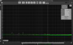
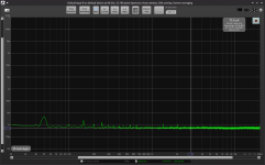
I have also done it with the NoNoiser (with CCS), and brought the noisefloor level of the regulator to around 330pV/sqrtHz level (with ZTX951), or about 46nV in audio spectrum. Seems the same at -5Vout and -12Vout. PSRR (at 100Hz) was over 140dB at -12V and a bit shy of 140dB at -5V.
The attached measurements contain my LNA's noise, about 63nV in audio spectrum (~440pV/sqrtHz).
I didn't have stability issues (edit: in its latest form) but I will make a new set of measurements for a revision of the PCBs I already ordered.
The attached measurements contain my LNA's noise, about 63nV in audio spectrum (~440pV/sqrtHz).
I didn't have stability issues (edit: in its latest form) but I will make a new set of measurements for a revision of the PCBs I already ordered.
Attachments
Last edited:
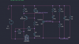
This design could be easily converted into a CCS Denoiser. Trileru did suggest some parts changes, but it doesn't seem to change anything in noise, psrr or impedance. A simple connection between the junction of the transistors collectors with adjust pin, through capacitor and diodes, would convert it into a Denoiser and improve things for more than the better.This is not a denoiser: it is a dedicated regulator I designed/adapted for a member.
It does work, it has been tried and tested, and its main advantage is its extremely low dropout (with a suitable pass MOS).
It has good overall characteristics (it cannot match a denoiser though), but it is a voltage regulator, meaning it cannot ensure a soft start with cold tungsten filaments.
In general, this shouldn't be a problem, since tubes can normally handle the cold current inrush, but you have to make your own opinion about it.
Note that regulators including a 317 struggle to cope with the cold filament resistance, and often fail to start properly
I did simulate the regulator as it is, which had awful results, as Elvee predicted. The input CRCLVRC is more than overkill: it's unnecessary. On the Denoiser, and even more with the NoNoiser, you can use simpler RC or CRC filters, with small cap values. The CRC resistor value will depend on hom much the transformer can provide, but the higher resistor value the better. But this doesn't affect the performance of this regulator.
I have been trying different discrete regulators all week, and on them you can see improvements on the simulation with CRC or CLC filter. That is not the case with the Denoiser, according to LTSpice, improvements are less important. But in any case, actual measurements are essential.
Any chance we get an .asc of it? I imagine it could be adjusted for higher voltages, like 60v or so?
OK, I went ahead and simulate. Here are the .asc for noise, psrr and impedance. It's superb!
Noise average: 7nV
Impedance average: 2 microohms from 10Hz to 20KHz.
PSRR average: less than -94dB from 10Hz to 1MHz.
Fantastic job, Trileru!
1) Are you planning to assemble it soon and check the simulation results?
2) What Mosfet can be used for the positive version. I couldn't find the complementary for the one you used. Other Mosfets that can be used? That MOSFET is out of stock on Mouser, as are so many active parts. We are on a semiconductor drought! Aliexpress parts, particularly semiconductors, are most probably fakes.
3) Up to what voltage can this reg be used? What changes, besides R6/R7 should be implemented? The TL431 and BC557 can't take the voltages I'd need for an amplifier low current supply, averaging 65v. The specs I got are better than those from any discrete regulator I simulated.
4) Many people should be interested in a +/- 15v version.
Attachments
OK, I found the closed thread where Elvee suggest this regulator I uploaded the simulation .asc files.
https://www.diyaudio.com/community/...for-high-current-consumer.329949/post-5603233
Was it you, Elvee, that designed it?
Remember the discrete regulators you helped me with for a Luxman power amp? Could this schematic be adapted to 70v-60v input and output? The critical part is the LT431, that couldn't handle such high voltages.
Yes I did. I never tested it in the real world for 8.3V, but I adapted the values from the initial design, and it worked well for the recipient.Was it you, Elvee, that designed it?
You could use Mark's solution, but you need to size the zener with a reasonable accuracy for the target voltage. A more universal method would be the insertion of a cascode, but it requires an additional transistor, + its base biasing network.Remember the discrete regulators you helped me with for a Luxman power amp? Could this schematic be adapted to 70v-60v input and output? The critical part is the LT431, that couldn't handle such high voltages.
Note that this circuit was optimized for high-current/low-dropout. You are free to use it for other purposes (as are all of my designs), but I have designed a number of highish-voltage regulators, some fully discrete, some IC-based which are probably more sensible choices for your purposes; some even fall into the low-dropout category, even though they are high-voltage.
I am not going to attempt to locate them, because most of them are answers to other members posts, and the search function of the forum is a PITA, but if you are motivated enough, you can probably find them (preferably use google or another search engine).
I certainly have them stored somewhere, on various computers, USB drives, etc. but retrieving them would also be a major task too as I am not a particularly disciplined and ordered person.
Hi, i have a circuit feeding a preamp with 78m15 and 79m15, do you think the denoizer will work here?

The dienoiser should work: it can drive a low impedance, which will be required here. I don't think the distinction between regular 78, 78M or 78L matters much. Try it in improvised manner first, with flying leads and a kludged dienoiser, and if it works, do it properly
For measurements using ARTA with an external USB sound card do you use AC or DC coupling (with the appropriate LNA and/or padding )?
TYVM.
TYVM.
Disregard my previous question - found the answer here:
https://www.analog.com/media/en/technical-documentation/application-notes/an83f.pdf
https://www.analog.com/media/en/technical-documentation/application-notes/an83f.pdf
- Home
- Amplifiers
- Power Supplies
- D-Noizator: a magic active noise canceller to retrofit & upgrade any 317-based VReg