

Good ! That's deffinitely a better use for lm317! You'd probably get good curves with only one 2sa1943 too at lower currents than 5 A as for 37v it should perform ok. Most probably nobody would use a linear regulator today over 3A .
Last edited:
On further investigation seems that the CCS NoNoiser should be able to use a red LED instead of the IR one, in the CCS. There's an extra Vbe in the mix so that would mean ~1.8V min Vdrop across CCS, which should allow for a red LED to be used.
Denoisator still needs an IR LED.
Denoisator still needs an IR LED.
Last edited:
My load is the heaters of a 307A vacuum tube 5.5V 1A, without denoiser I measure 2-3mVAC, I have read heaters like better current regulators & gyrators, the question is worth the work & money to make & use the denoiser between the LM317 reg. & the 307A heaters, if yes what kind of reduction of ripple I have to expect? At schematic R5 0R55 is the load, right?
TIA
Felipe
TIA
Felipe
Attachments
Last edited:
Hi!
I im designing mini PSU PCB for my next project and that is to supply quiet, clean and nice PSU for my preamp.
Using double secondary windings, and RCLC filter to suppress low and high frequency noise that is coming from 230VAC outlet.
Can you please @Trileru simulate in LTSpice and see if i need to add or change resistor value?
I need this PSU with:
Also if you could add two resistors to make function of REMOTE SENSE, this way i connect at preamp force and sense wires and i got same performance on preamp like this psu denoiser circuit is close to preamp.
My wires that will go from force to preamp si 20cm long, so i need remote sense to get same performance as wire is 1cm long.
I im designing mini PSU PCB for my next project and that is to supply quiet, clean and nice PSU for my preamp.
Using double secondary windings, and RCLC filter to suppress low and high frequency noise that is coming from 230VAC outlet.
Can you please @Trileru simulate in LTSpice and see if i need to add or change resistor value?
I need this PSU with:
- 24VDC out at load and idle
- it needs to get from 50mA to 200mA output @ 24VDC for preamp, tone control, source selector and other stuff to supply
- i added two resistors in parallel to get exactly 24,0085VDC (i im using RN60D resistors that is 100ppm and 1% so voltage at output need to be exactly 24,00VDC)
- low noise (below 1nV/sqrt(Hz), low impendance (in a range of uOHM), high PSRR (-150dB++), and i added HMLP-6000 RED LED 1,8VDC Vf, that diode from test Gehard test it gives 0,27nV/sqrt(Hz) when bias is 6mA...so if you could put this model into simulation to see if there needs any tweaks about resistor values.
- i added 10nF MKP1837 capacitor, on schematic is 3,3nF...does 10nF worse regulator performance?
Also if you could add two resistors to make function of REMOTE SENSE, this way i connect at preamp force and sense wires and i got same performance on preamp like this psu denoiser circuit is close to preamp.
My wires that will go from force to preamp si 20cm long, so i need remote sense to get same performance as wire is 1cm long.
Attachments
This is not a denoiser: it is a dedicated regulator I designed/adapted for a member.My load is the heaters of a 307A vacuum tube 5.5V 1A, without denoiser I measure 2-3mVAC, I have read heaters like better current regulators & gyrators, the question is worth the work & money to make & use the denoiser between the LM317 reg. & the 307A heaters, if yes what kind of reduction of ripple I have to expect? At schematic R5 0R55 is the load, right?
TIA
Felipe
It does work, it has been tried and tested, and its main advantage is its extremely low dropout (with a suitable pass MOS).
It has good overall characteristics (it cannot match a denoiser though), but it is a voltage regulator, meaning it cannot ensure a soft start with cold tungsten filaments.
In general, this shouldn't be a problem, since tubes can normally handle the cold current inrush, but you have to make your own opinion about it.
Note that regulators including a 317 struggle to cope with the cold filament resistance, and often fail to start properly
Note that regulators including a 317 struggle to cope with the cold filament resistance, and often fail to start properly
Is this the case for LM338 as well? Does it have to do with their (stock) output impedance?
@ronovar
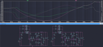
The LM3x7 + denoiser part seems right with a few mentions.
Q2/Q3 don't have to be ZTX, you don't gain much if anything from using them instead of BC3x7 pair in that spot. Maybe use them for another set of denoisers. But if you have more of them you could use them in the CCS circuit as well.
C16/C19 don't have to be 10nF, that's a bit on the high side. Should work fine with 3.3nF.
LED1/LED2 should have ~2.4Vdrop so maybe a yellow LED. Or 5x1N4148 diodes in series. 1N4148 seemed to work better in my tests, as in a bit lower startup initial swing with 1N4148, but should work fine with LED as well.
R15/R18 should be set such that Vce of Q1/Q4 is at about 1/5th of yellow LED/diode string Vdrop bellow ADJ pin, so 2.4/5=0.48V. In this case R15's value is closer to 590-600K value, but this will have to be tweaked at assembly. R18 seems to be around 560k area, going by the LTSpice sim with your BJTs.
C17/C18 fine as value just make sure the C17 has 200-300mOhm ESR and C18 maybe 200mOhm max, try 50-100mOhm if you can, in my tests LM337 + denoiser circuit liked low ESR output caps.
C14/C20 don't user higher than 22uF.
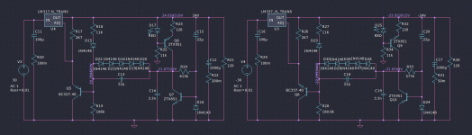
For even better performance you can try the NoNoiser version. You could design it into the PCB and test it out if you want, then revert to the simple CCS Denoisator by shorting B-E of the extra BJT and also shorting the extra 1N4148 diode. You could also use red LEDs for the CCS in NoNoiser case. IR also works fine, with red you'd have to adjust the CCS resistors values as shown in the attached schematic.
Now, regarding your questions.
Not sure how precise you're going to get it with two resistors in parallel. Vout varies a bit from part to part. OUT-ADJ voltage (1.25V) has a +/-50mV rating in datasheet. For precise Vout I'd use a pot. Or make sure that you actually need very high precision for those 24V.
LED/diode string across the coupling cap only slightly conduct at startup, after startup they don't do anything. Their noise is irrelevant in that position.
LED from CCS doesn't need to be anything special. Any ~1.1Vdrop IR or ~1.7Vdrop red LED will do. I don't think you'd see any change if using a certain LED model.
10nF is on the high side, affects the higher frequency PSRR performance. 3.3nF worked fine in my tests.
If you use the NoNoiser version I don't think you need the CRC filter, unless you need to share the heat between LM3x7 and that resistor.
Remote sensing in this case is not for DC, but for AC. I recommend sensing at the output of the supply board connector. If the preamp's PCB design is not making things worse you will have low noise at the load. In my experience using sense leads for remote AC sensing is complicating things. You're better off with using an addon board at the load with a longer ADJ wire than running sense wires from the supply board to the load. The most practical approach for me was to design the sensing in the supply PCB, and have it on the output connector and I very recommend this approach.
Lastly but not least, I don't see any reason for not using LM317 as well for negative side, with dual secondaries.
Also maybe design a series resistor for the output capacitor for any LM317 application. This way you have a larger selection of even lower ESR capacitors that you can increase the ESR with the series resistor.
Attachments
Hi Guys,
I think I read somewhere that it is not recommended to put the diode bridge on the same PCB of the regulator/nonoiser. It's true? thank you Maxpou
I think I read somewhere that it is not recommended to put the diode bridge on the same PCB of the regulator/nonoiser. It's true? thank you Maxpou
In a commercial project, making them coexist is possible with extreme care, in-depth analysis and tests, since multiple modules add to the cost, but for DIY the simplest way to avoid problems is distance, meaning separate PCB's.
There are hundreds of ways for unwanted noise to sneak into a circuit, and E-field strength decrease as the square of the distance and H-field as the cube. Increasing the separation is thus a no-brainer, unless you have other constraints
There are hundreds of ways for unwanted noise to sneak into a circuit, and E-field strength decrease as the square of the distance and H-field as the cube. Increasing the separation is thus a no-brainer, unless you have other constraints
Hello ElveeIn a commercial project, making them coexist is possible with extreme care, in-depth analysis and tests, since multiple modules add to the cost, but for DIY the simplest way to avoid problems is distance, meaning separate PCB's.
There are hundreds of ways for unwanted noise to sneak into a circuit, and E-field strength decrease as the square of the distance and H-field as the cube. Increasing the separation is thus a no-brainer, unless you have other constraints
You mentioned earlier that the denoiser cannot use a 100nF ceramic capacitor at the output, and a local decoupling capacitor can be used if the load is far away from the output.
I looked at my PCB and the load wasn't far enough from the denoiser output, but the load was a 30MHz high bandwidth device that had to be locally decoupled using a 100nf capacitor to work properly.
Can I connect a 0.1R resistor in series between a 100nf capacitor and a 100uf capacitor? Is there a better solution?
Thank you!
directly at the output, you will have a 47 or 100µ Ecap. If you increase the value of the local bypass to 100µ, you will be in the acceptable range (and improve the bypass quality for your 30MHz load)
Do you mean that 30MHz high-frequency decoupling can be completed directly using 100uf ECAP without using a 100nf ceramic capacitor ?directly at the output, you will have a 47 or 100µ Ecap. If you increase the value of the local bypass to 100µ, you will be in the acceptable range (and improve the bypass quality for your 30MHz load)
@Trileru Thank you for making these simulations. I noticed that you made LTSpice simulations for 21st century Maida regulator LT3080 and used older scheme for that. Could you please run simulations with a modified 21st century Maida scheme that is available here?
https://www.diyaudio.com/community/threads/21st-century-maida-regulator.209067/page-9#post-3515776
I read an article about improving PSRR where they said that putting LDO-s in series doubles the PSRR at any given frequency (assuming identical regulators).
https://www.analog.com/en/technical...ersupply-rejection-for-linear-regulators.html
What are other users thought and experiences about this? Could you please make some simulations in LTSpice for 21st century Maida scheme and maybe you have some LV scheme with LT3045 to also make series simulations with this LDO?
Thank you!
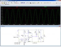
I made a rough draft out of curiosity but have no idea if it would be stable or not. I used Elvee's original Denoisator design and that 43.7k resistor would have to be a 5W one as it dissipates some heat. I chose a low Vce for denoiser BJT. A CCS could maybe be used but it would have to be some higher power BJT. Or maybe the denoiser BJT could be replaced with a higher voltage one and raise Vce.
As the simulation is there's a bit of a startup overshoot of around 5V or so. PSRR seems extremely high.
As the simulation is there's a bit of a startup overshoot of around 5V or so. PSRR seems extremely high.
Attachments
@Elvee
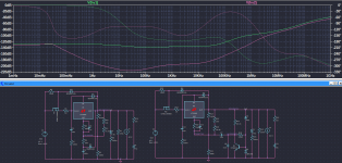
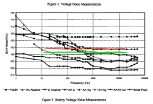
I found this older article of battery types noise measurement:
https://tf.nist.gov/general/pdf/1133.pdf
And I drew the (measured) noisefloor of the CCS NoNoiser and also of my discrete design. The NoNoiser is the red trace.
I was wondering, is it possible to parallel two BJTs in the denoiser circuit? In LTSpice I get lower noise with two paralleled BJTs in CCS Denoisator configuration than with a single BJT in CCS NoNoiser configuration. But I have to increase the total current through the denoiser circuit. With matching would it be feasible for ~8mA through each?
Attachments
- Home
- Amplifiers
- Power Supplies
- D-Noizator: a magic active noise canceller to retrofit & upgrade any 317-based VReg