Yes but...these modern chips were mainly designed for modern low voltage high frequency applications.A modern dac let's say needs multiple different voltage supplies , all of them lower than 5v and you can't use multiple dienoisers based on lm317 in such a circuit due to space constraits.So for a modern digital circuit it makes more sense to use a general smps followed by multiple specialized ldo's and there are tons of them...My Audient soundcard is using a special low noise smps that deliver 100uv of noise and it doesn't use any other ldo's after it for powering the +_12v analogue rails, while the digital circuits have their own specialized regulators...
Last edited:
I do not recommend you use lm317 in the digital part of the DAC if you want to eliminate HF noise.
This project was always stated as useful for analog stuff, powering opamps etc. There's many dacs/preamps that use LM317/LM337 combo for +- 5/12/15V rails for opamps. The discussion has never been that the denoiser is the new king of the hill for everything possible related to audio gear. It's just really nice to get something more out of old gear, or you can't afford the new stuff and for a 1-2 bjts and some resistors you get more performance out of a vanilla lm317.
One may also try his hand at a good layout for nicer gear if one wants to, specially in spite of the gold on black audiophile lt304x modules.
Having the lt3042 regs on a nice board with a nice layout and using an add-on in an unknown lm317 circuit is hardly a fair comparison no?
Looking back at the first post in this thread I believe these denoisers were actually meant to be used as add-ons to existing LM317 power supplies. And I would expect the layout to be not that critical considering Elvee's test builds 😀
But instead of arguing what's stopping you to build yourself these denoisers that you have presented.
the truth was revealed right on the start page of this topic 🙂Summary: low noise voltage regulator achieved using twelve electronic components, one of which is an integrated circuit.
But instead of arguing what's stopping you to build yourself these denoisers that you have presented.
Well time. I did the denoisers layouts in the time I have between normal life and designing my DAC. It wasn't lost time, as working at the denoiser boards I understood the circuit better and in the end I know better how to integrate it in my project.
I did find a blank board in the drawer and also found my etcher, just need to find some time to tinker/drill etc.
This is not a circuit that is made as an add-on, this is a circuit, and Elvee recommended you could use it as an add-on for non-critical applications. That does not mean one can't design it in a new application. You can do whatever you want with it 🙂
Also the only circuit he recommended as an add-on is the denoiser, and you've seen first hand why. You've made that add-on and the dienoiser wasn't stable, just the denoiser part of it. I don't know how you did yours, but I tried to follow Elvee's recommendation of having the compensation network as close as possible to the bjt pins. That may help oscillations, but it's not guaranteed. Worst case scenario people are left with a denoiser instead of a dienoiser. That should be stable.
i don't think i would've ever tried anything like that, not even for analog stuff... 🙂I do not recommend you use lm317 in the digital part of the DAC if you want to eliminate HF noise.
.
I have an AK4396 DAC that I got from ebay in kit form. Replaced all caps but still Vref/VACC is the chinese supplied LM1117-5V that is fed by a 7812. And it sounds nice, I don't have any hiss or noise, and from time to time while doing stuff at home and listening to music I have moments where I stop what I'm doing and think "damn, sounds great!" and I mean the end result. There's moments where the quality of the sound takes me away from whatever I'm doing, I stop and I listen for a while.
There's a point of diminishing returns. The way I see it is you have to make it good enough and also try to not shoot yourself in the foot (by using LT304x modules willy nilly just because they are expensive and the IC has nice specs so it must be better where I put it!).
The reason I'm doing the DAC is I want to remove the active crossover and have DSP so I can correct the speakers and maybe the headphones. Also to get a sub output. There's a few caps in the signal path in the active crossover, this way I'm left with the signal going through only the input caps from the amp.
The spikes are some kind off artefact: the denoiser can only generate a continuous noise spectrum, and discrete frequencies must result from instability, external noise sources, etc5. LM317 at 6V with denoiser. Still further improvement. However the spikes are bothersome.
I think that the comparison between a 200 mA device (LT3042) and a 1.5A device (LM317) is completely pointless---they are for totally different applications. Do you really think anybody can HEAR the difference between -140 db and -160 db?
true -90db PSRR, CMRR, THD+N ... is enough for everything.When i see better than that i skip...
The spikes are some kind off artefact: the denoiser can only generate a continuous noise spectrum, and discrete frequencies must result from instability, external noise sources, etc
This is my assumption as well. However external noise sources are probably not the cause since LT30xx graphs do not have these even though the setup and location was exactly the same in all measurements. Instability is more probable. But all in all the spikes are at a very low level so they may go unnoticed. That is why I would like to see other denoisers measured.
So what, if you make a die that has lm317 + denoiser circuit on it in a plastic case then you approve of the device?
I have attached here the designs for the smd and diy tht add-ons for LM317 die/denoiser, and the diy versions for full power supplies for die/denoiser and nonoiser. The die/denoiser boards have a jumper across R3 to select between dienoiser and denoiser. There's also jumpers to bypass parts that are not needed, like across the resistor in series with C2. For the full board diy version you install a wire link instead of that resistor. There is also a jumper to short the series resistor from the compensation network for the die/denoiser boards.
The add-on boards have provision for a resistor in parallel with a cap from ADJ to GND. This should allow for the Diego schematic for use with fixed type regulators like 7812. This application of the dienoiser hasn't been tested by anyone so far so it might not work. The simpler denoiser circuit does not work as far as I remember.
Full boards have also a jumper across the series resistor for the output cap. That resistor is meant to correct the ESR of the output cap. If you use a low ESR cap, you need to bring the ESR up with that resistor. Somewhere in the 0.2R range should be stable, not guaranteed but there is a way to correct this way, to make it stable.
Full board designs have sense lines. If these are not needed you need to short the smd jumpers. Using them might make the regulator unstable so your mileage might vary, but they are there as an option.
Input filtering can be CRC or CLC. If using a resistor you need to calculate the value for an appropriate resistance depending on the current and how much voltage you can spare.
Theoretically it should work for LM337 negative regulators as well, you need to rotate some parts. I do not know which ones, but the info is in the thread. I can't offer much help for the negative regulator but maybe someone can chime in with the info. All I remember is that LM337 doesn't do well with I think the C2 series resistor, so you use the smd jumper for that.
For the Denoiser version you calculate the R2 value as you would normally do for LM317. For the Dienoiser it is the same just that you need to adjust R3 for the range of voltage you output. I have attached a screenshot from the post with the table of values. For the NoNoiser you need to calculate the value according to Elvee's formula, I have attached a screenshot of his post. I have also attached the values for R3 if using on 78xx type regulators, but again, that schematic has not been confirmed as working in practice, only simulations.
WARNING!!! These board designs have not been tested yet! You make them at your own risk!
Mods please delete the attachment files from my other posts, leave only the photos as they are informative.
Attachments
Last edited:
The spikes are some kind off artefact: the denoiser can only generate a continuous noise spectrum, and discrete frequencies must result from instability, external noise sources, etc
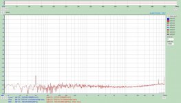
I think I found the culprit. Whoever designed the LM317 power supply (acting as a DAC pre-regulator) was following the latest diy-trend of that time (about 2005) and used ground power planes. These apparently act as antennas that pickup small noise artefacts. I made a quick&dirty new LM317 regulator (without any ground planes) and the spikes were gone. Here is the new graph.
Attachments
 Posts containing personal remarks and arguments have been deleted. Anyone posting more of the same will find himself muted for at least a week.
I think I found the culprit. Whoever designed the LM317 power supply (acting as a DAC pre-regulator) was following the latest diy-trend of that time (about 2005) and used ground power planes. These apparently act as antennas that pickup small noise artefacts. I made a quick&dirty new LM317 regulator (without any ground planes) and the spikes were gone. Here is the new graph.
Thank you looks great.
Is it stable and have done any listening?
Thank you looks great.
Is it stable and have done any listening?
Yes, it is stable as is. Haven't yet used it in any real application.
- Home
- Amplifiers
- Power Supplies
- D-Noizator: a magic active noise canceller to retrofit & upgrade any 317-based VReg