With schematic in the post #1092 the load regulation is lost when compared to the positive regulator. From this schematic load regulation is better by moving the lower resistor of the resistor divider to the anode of the TL431 ( instead of the PSU output ). This is proved in the posts where I give the equations for the output voltages in these different solutions, post #1093 #1094. Why it is better is clear in the equations.My goal is explained in the post #1092. Based on the actual chosen semiconductors, some part values may differ and schematics may be altered. As said, it is close enough.
Moving this resistor gives no loss about the benefits from the denoiser.
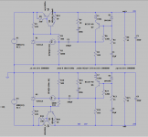
#1092 is referenced for the goals
#1116 contains corrected circuit
results for both positive and negative regulator are well matched
#1116 contains corrected circuit
results for both positive and negative regulator are well matched
The current mirror has the potential to give a negative regulator that has exactly the same behavior as the positive regulator. This is true assuming an ideal current mirror. This result is confirmed in simulation using a 2 transistors current mirror, where I get very near the same results about load and voltage regulation, PSRR, Zout, noise.As for the current mirror, unanswered question is why to use this implementation? What are the benefits, how is load and voltage regulation? In my intended usage scenario with 1,5 V headroom this works weird.
In the attached simulation, positive and negative regulator results are well matched.
Stability from simulations is highly questionable, whatever solution. Fiddling with component values to get stability can be misleading.
Last edited:
Had some PCBs made using tombo56's gerbers from post #939:
https://www.diyaudio.com/forums/pow...fit-upgrade-317-based-reg-19.html#post6255032
Will show progress soon.
https://www.diyaudio.com/forums/pow...fit-upgrade-317-based-reg-19.html#post6255032
Will show progress soon.
Last edited:
Please give me an image of the corrected circuit. Presently with my smartphone, I don't have the simulator to load the .asc.#1092 is referenced for the goals
#1116 contains corrected circuit
results for both positive and negative regulator are well matched
Ok. I like my old notebook so much with WinXP 🙂
The good about XP is no upgrade. Finally a stable debugged Microsoft OS.😉
You are using the TL431 as a zener in both regulators.
Then load and voltage regulation is governed by the Vbe + 10 ohm of the driver transistor. Why you added this 10 ohm ? ( re is proportional to Ic, 26 ohm at Ic = 1mA).
Have you looked at the max current and power at the TL431 that occurs in the case of: No load on the PSU and max mains voltage ( +10% ). Life is easier for the TL431 at max load that gives a max of unregulated voltage droop.
You added an inductor at the transistor of the denoiser, a bead I presume, isn't redundant with the compensation at the collector, do they add ?
OK. Please, present solution with LM regulators that delivers:
Several A output
Over 100 dB PSSR at that currents
Stability with capacitive load ESR from 2 mΩ to ohm range
0,1 uV total noise
Much less than 1 mΩ impedance up to 1 MHz
Fast transient response
All that with only 1,5 V drop
If you change the "LM" to "LT" it becomes easy. LT3042/45 or LT3094 with external BJT achieves (or surpasses) all the above goals 😀
LT3094 is -20V 500mA.If you change the "LM" to "LT" it becomes easy. LT3042/45 or LT3094 with external BJT achieves (or surpasses) all the above goals 😀
How do you fit a BJT for more output current.
I did not find how in the datasheet.
How about voltage ? I need 32V output.
LT3094 needs an output capacitor > 10uF with ESR< 0.03 Ohm and ESL<1.5nH.
Last edited:
When you need 32V you can forget using LT3045.
How to use a pass transistor is the same as with LT3045.
How to use a pass transistor is the same as with LT3045.
Adding a pass transistor for a higher current drive.
The application informations in the datasheet doesn't show how to do it.
May be that is too obvious.
May be it clubbers the high performances.
The application informations in the datasheet doesn't show how to do it.
May be that is too obvious.
May be it clubbers the high performances.
Please remember that Elvee's original circuit is just an add-on to existing LM317 power supplies. It was not meant to be an example of a complete PS.
Thanks for thorough response bohrok.
Of course to no one's surprise my first attempts didn't fly. 24VIN only seeing 1.29VOUT. I did throw in a fresh LM317 in case I ESD'd the first one during construction.
I take it this is the LM317 keeping VOUT above the ADJ pin which does show 0V.
Is this what it looks like when Q1 is dead? I might pop in a fresh MPSA06 see if that works quick and easy before I dive into the mess on the bottom side of the PCB.
Only other thing I can see (of course I don't see very well) is the 5K trimpot at R2 which I connected wiper to ADJ, one of the other pins to GND and the other NC. Not sure if this is correct, pots are my archnemeses.

Last edited by a moderator:
Adding a pass transistor for a higher current drive.
The application informations in the datasheet doesn't show how to do it.
May be that is too obvious.
May be it clubbers the high performances.
You could check the datasheet of LT3045/LT3042 and also conclude that nothing is written about using pass transistors.
But you can read it here:
Increasing Output Current of the Ultralow Noise, Ultrahigh PSRR LT3042 200mA Linear Regulator | Analog Devices
It seems there is hardly any competition left for regulators with a maximum output voltage of 20V with regards to noise. The slightly less high performance with pass transistor still is way better than any of the old dinosaur regs.
I have built several PSU's for DACs and streamers with single LT3045, 3 in parallel and some with pass transistor and there really is no valid reason to not use LT3045 (or TPS7A4700). If you want performance that is. The circuit of Elvee is meant to upgrade existing designs. In new designs LM317 should be avoided. It is probably easy of use and nostalgia that it is carved in the minds of audio guys. Make the switch as it is an easy upgrade to better audio performance!
IMO the largest drawback of the pass transistor is the dropout voltage now being 1.5V. Last week this got me into trouble with a LT3045 5V PSU powered by a 6V transformer.
Last edited:
jebivetar,
If you measure about 1.25V between ADJ and Output, this means LM317 works fine.
If you measures 0V at the ADJ, this means the 5K trimpot is set wrong or there a short.
Set the 5K trimpot half way and see what you get
If you measure about 1.25V between ADJ and Output, this means LM317 works fine.
If you measures 0V at the ADJ, this means the 5K trimpot is set wrong or there a short.
Set the 5K trimpot half way and see what you get
Thanks, an interesting article that gives the answers to my questions.
Jean Paul - yes you’re correct that the ‘competition’ in the 20 v or lower area has been pretty much run to completion. And we have good articles how to boost output currents too.
The question is if there is (similarly) good performance available for higher voltage (say 36v or 48v) ? Anyone any suggestions ?
The question is if there is (similarly) good performance available for higher voltage (say 36v or 48v) ? Anyone any suggestions ?
Of course to no one's surprise my first attempts didn't fly. 24VIN only seeing 1.29VOUT.
Maybe you should debug by first setting up a regular LM317 PS without denoiser. Just connect C3 negative terminal to ground.
If you change the "LM" to "LT" it becomes easy. LT3042/45 or LT3094 with external BJT achieves (or surpasses) all the above goals 😀
Almost, but not quite: 40V input and I don’t think it would play nice with several 10.000 uF low ESR capacitors at the output, as is usually found in the regular CRC power supply of a class A amplifier.
I find this as interesting development challenge and entertainment (popcorn not included), that eventually could be used in my amplifier builds.
Finally, how would LT regulator answer the concerns expressed in the neighboring thread? 😀 😀
Are you really fine with IC voltage regulators ?
Why you added this 10 ohm ? ( re is proportional to Ic, 26 ohm at Ic = 1mA).
It helps prevent oscillation and ringging if regulator is "smacked" with high and fast transient load.
You added an inductor at the transistor of the denoiser, a bead I presume, isn't redundant with the compensation at the collector, do they add ?
It works together with RC compensation in the same direction achieving slightly better result.
- Home
- Amplifiers
- Power Supplies
- D-Noizator: a magic active noise canceller to retrofit & upgrade any 317-based VReg