protoboard goulash post mortem
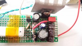
So I'm not sure what actually solved my problems, I checked the schematic against the board and the board against the schematic and found nothing wrong. I did swap out the 180K resistor for a larger one that got it closer to the BJT, and also the "ground plane" between attempts.
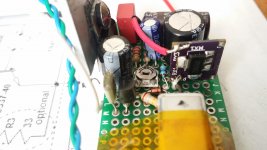
Think it's all salvaged parts except the Wima, the diodes, a couple of the resistors, and the LM317. 470uF on input (Chemicon KY) and output (Rubycon YXA). I didn't like how far away the output cap was so I placed a 470nF Wima to the LM317 output pin from the bottom. I also added a capacitance multiplier board to the input, per one of Mark Johnson's comments I saw somewhwere else.
The 39ohm cement resistor gets me a drop from printer power brick's 30v to 23v, and the CapMx gets me another 2 volts, so the LM317 only has to do 21v to 18v. I did feel like the sound quality improved after each of those, but surely to no one here's surprise the whole thing doesn't work very well. Think it's my first audio protoboard goulash so lesson learned.
Sound is very flat and noisy compared to my canonical solution of "random switched input" -> self designed MT3608 boost and CapMx boards -> 2200uF/.47ohm CRCRC -> load. I listened to the Denoiser powered amp while I built another one of those, and using it with a RaspberryPi ACDC brick after I finished, the difference was immediate and obvious - MT3608MxCRC solution is completely silent with no input, and the sound has more energy and dimensionality.
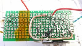
I'll chalk it up to my construction. I'm all ears if anyone has any simple ideas on how to improve it. Maybe getting rid of the copper subway system in favor of 2/3 precise ground wires? It's an elegant little circuit so I might give it another shot, maybe on a stripboard as I've never used one before and the layout seems conducive to that.
So I'm not sure what actually solved my problems, I checked the schematic against the board and the board against the schematic and found nothing wrong. I did swap out the 180K resistor for a larger one that got it closer to the BJT, and also the "ground plane" between attempts.
Think it's all salvaged parts except the Wima, the diodes, a couple of the resistors, and the LM317. 470uF on input (Chemicon KY) and output (Rubycon YXA). I didn't like how far away the output cap was so I placed a 470nF Wima to the LM317 output pin from the bottom. I also added a capacitance multiplier board to the input, per one of Mark Johnson's comments I saw somewhwere else.
The 39ohm cement resistor gets me a drop from printer power brick's 30v to 23v, and the CapMx gets me another 2 volts, so the LM317 only has to do 21v to 18v. I did feel like the sound quality improved after each of those, but surely to no one here's surprise the whole thing doesn't work very well. Think it's my first audio protoboard goulash so lesson learned.
Sound is very flat and noisy compared to my canonical solution of "random switched input" -> self designed MT3608 boost and CapMx boards -> 2200uF/.47ohm CRCRC -> load. I listened to the Denoiser powered amp while I built another one of those, and using it with a RaspberryPi ACDC brick after I finished, the difference was immediate and obvious - MT3608MxCRC solution is completely silent with no input, and the sound has more energy and dimensionality.
I'll chalk it up to my construction. I'm all ears if anyone has any simple ideas on how to improve it. Maybe getting rid of the copper subway system in favor of 2/3 precise ground wires? It's an elegant little circuit so I might give it another shot, maybe on a stripboard as I've never used one before and the layout seems conducive to that.
Attachments
Last edited by a moderator:
This is highly dependents of the load.The 39ohm cement resistor gets me a drop from printer power brick's 30v to 23v, and the CapMx gets me another 2 volts, so the LM317 only has to do 21v to 18v.
Fine if the current draw is near constant. More current will drop the 23V then you will have less than 3V drop at the LM317.
If it doesn't run hot, setting more than 3V might make it run happier.
Load is ~150mA constant current.More current will drop the 23V then you will have less than 3V drop at the LM317.
It's a little bit higher than 3.00v, maybe closer to 3.5v - you don't think that's enough headroom for 150mA? The heatsink gets slightly warm.If it doesn't run hot, setting more than 3V might make it run happier.
From the datasheet:
3-V headroom is recommended (VI – VO) to support maximum current and lowest temperature.
To play it safe, I would put 4V or 5V.
3-V headroom is recommended (VI – VO) to support maximum current and lowest temperature.
To play it safe, I would put 4V or 5V.
LT1431 negative voltage regulator ….
… as proposed by member Shinja, didn’t live up to the expectations. It works but has some drawbacks. Load regulation is not very good. It needs minimum 2,5V dropout to work. PSSR is not as good as with positive voltage version but is still 100 dB. Output impedance is around 0,3 mΩ.
I tried several different configurations but it couldn’t be made better, at least by me.
It is a viable solution but I have a better proposition.
Attachments
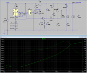
And now, something completely different
No, it is the same as all previous circuits based on the adjustable voltage reference. 🙂
Just, voltage reference is made of discrete components. LED as voltage reference is widely used in many solutions presented here and solves the problem of making proper negative voltage reference. LED is temperature compensated and biased with temperature compensated CCS, so this should be acceptable for temp. range in which power supplies operate.
Adjustable voltage reference is made by adding an opamp and a standard voltage divider. Nothing new to see here, move on. 🙂
Opamp can operate up to 60V, so this is top operating input voltage. Over 40V, there will be some startup protection of LM334. Exchanging OPA551 with OPA454, same design can be used up to 100V input voltage, replacing some semiconductors and adjusting some resistor values.
What this design provides:
Seems, that conditions to make small add-on module that replaces resistor in usual CRC power supply, and transforms it to super PS, are satisfied.
No, it is the same as all previous circuits based on the adjustable voltage reference. 🙂
Just, voltage reference is made of discrete components. LED as voltage reference is widely used in many solutions presented here and solves the problem of making proper negative voltage reference. LED is temperature compensated and biased with temperature compensated CCS, so this should be acceptable for temp. range in which power supplies operate.
Adjustable voltage reference is made by adding an opamp and a standard voltage divider. Nothing new to see here, move on. 🙂
Opamp can operate up to 60V, so this is top operating input voltage. Over 40V, there will be some startup protection of LM334. Exchanging OPA551 with OPA454, same design can be used up to 100V input voltage, replacing some semiconductors and adjusting some resistor values.
What this design provides:
- It operates starting with 0,15 V dropout with 100 dB PSSR
- At 0,3 V dropout with excellent 130 dB PSRR
- At 0,5 V better than that.
- Output impedance is 100 µΩ up to kHz range, and slowly rises to milliohm range at higher frequency.
- Noise is ridiculous to even mention.
- Transient response is very good.
- It can supply several A
- It is stable with small or big capacitance at the output if ESR is 150 mΩ or lower.
Seems, that conditions to make small add-on module that replaces resistor in usual CRC power supply, and transforms it to super PS, are satisfied.
Attachments
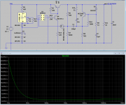

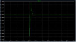
Actually, it works with full 140 dB PSRR at only 0,25 V dropout and doesn’t need more
While tidying up LTSpice schematic before publishing, I made accidental mistake and connected R17 & R18 to the wrong point. Didn’t notice while taking measurement screenshots. Here are actual PSSR results at 0.25 V dropout.
While tidying up LTSpice schematic before publishing, I made accidental mistake and connected R17 & R18 to the wrong point. Didn’t notice while taking measurement screenshots. Here are actual PSSR results at 0.25 V dropout.
Attachments
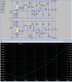
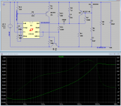
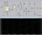
Replace R3 with a high compliance current source and PSRR will increase. Install a passive lowpass filter between incoming supply and OPA551 supply pin, and PSRR will increase {it won't show up in simulation, only in real life, cuz simulated PSRR of OPA551 is infinity, due to model limitations}.
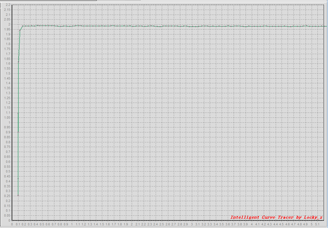
Here's a current source I built and put on a curve tracer, a couple weeks ago. Its current is reasonably constant all the way down to about 0.15V. Since R3 has =approx= 0.6V across it (VBE): plenty.
Click on the image to see it full size.
Here's a current source I built and put on a curve tracer, a couple weeks ago. Its current is reasonably constant all the way down to about 0.15V. Since R3 has =approx= 0.6V across it (VBE): plenty.
Click on the image to see it full size.
Adding an RC filter to the supply pin is fine advice as right now the opamps are also not decoupled.
Last edited:
Replace R3 with a high compliance current source and PSRR will increase. Install a passive lowpass filter between incoming supply and OPA551 supply pin, and PSRR will increase {it won't show up in simulation, only in real life, cuz simulated PSRR of OPA551 is infinity, due to model limitations}.
Mark, thank you for those “real word developer” advices.
Adding an RC filter to the supply pin is fine advice as right now the opamps are also not decoupled.
LTSpice simulation misses some other elements as well, as there was no effect in adding them. Real circuit will have opamp decoupled.

Ha ha I develop the other way around so only real circuits in many revisions 🙂 Never used LTspice or any simulation at all.
Then, you are a poster model for the “real word developer” as opposed to the LTSpice fantasy world. 😀
Replace R3 with a high compliance current source and PSRR will increase. Install a passive lowpass filter between incoming supply and OPA551 supply pin, and PSRR will increase {it won't show up in simulation, only in real life, cuz simulated PSRR of OPA551 is infinity, due to model limitations}.
Here's a current source I built and put on a curve tracer, a couple weeks ago. Its current is reasonably constant all the way down to about 0.15V. Since R3 has =approx= 0.6V across it (VBE): plenty.
Click on the image to see it full size.
Can you show schematic how the CCS is made?
While tidying up LTSpice schematic before publishing, I made accidental mistake and connected R17 & R18 to the wrong point. Didn’t notice while taking measurement screenshots. Here are actual PSSR results at 0.25 V dropout.
Looks great.
Why do the pass transistor turn with collector in output?
Thx
Looks great.
Why do the pass transistor turn with collector in output?
Thx
Looks even better 😀
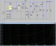
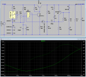
Here is result with RC filtering opamp supply line. To my surprise, OPA551 Spice model is better than usual and uses real PSRR. So, at usual First Watt A class bias of 1.3 A and 0,5 V dropout, model PSRR is 175 dB. If real circuit will have 20 to 30 dB worse, it will still be incredible.
PNP transistor with collector connected to the load is the only way to get low dropout. Minimal Vbe is 0,6 V. If NPN transistor, with emitter to the load side would be used, then minimal theoretical dropout would be 0,6 V. In practice it is 1 -1,5 V.
Conducting transistor can have Vce as low as 50 to 100 mV. So, regulator output voltage can be only 50 to 100 mV lower than input, where emitter is connected.
Attachments
Sorry, but what is the advantage of this regulator over the "traditional" denoiser and the dienoiser?
Wait a while before replying to give member carlmart plenty of time to read previous messages and understand their goals.
Can you show schematic how the CCS is made?
With some effort, schematic can be decoded from here posted picture:
https://www.diyaudio.com/forums/pow...al-noob-power-supply-noise-2.html#post6334599
MODERATORS:
Can't we please keep this thread focused on the ORIGINAL subject? That is, a noise canceller for LM317/337 regulators. If people want to discuss the 1431 and other regulator mods, please start another thread and stop polluting this one!
Can't we please keep this thread focused on the ORIGINAL subject? That is, a noise canceller for LM317/337 regulators. If people want to discuss the 1431 and other regulator mods, please start another thread and stop polluting this one!
- Home
- Amplifiers
- Power Supplies
- D-Noizator: a magic active noise canceller to retrofit & upgrade any 317-based VReg