Please have a look at this post, it summarizes such practical issues:
D-Noizator: a magic active noise canceller to retrofit & upgrade any 317-based V.Reg.
D-Noizator: a magic active noise canceller to retrofit & upgrade any 317-based V.Reg.
Elvee,
The raised question, which I also commented about mentioning your recommendation, is not quite paralleling other capacitors at the output, besides the 100uF or 270uD electrolytic, but bypassing or not the pins (or whatever) on what you are powering. Should you?
Of course we may say those caps are in parallel with the output, even if they are far from the board. But local bypass is considered important too, isn't it?
How should we proceed with local bypassing? Another electrolytic, instead of film or ceramic?
Not to look a gift horse in the mouth, but Hicoco's board design needs to be SMALLER. If someone could do that, it would be a great improvement in retrofitting Elvee's design.From the feedback it seems as though Hicoco's board meets all of the necessary criteria so I won't attempt to duplicate the work. A very nice and tidy layout too. I doubt I could do better.
I just checked, and my boards using your gerbers (thanks again!) shipped today! So arrival should (hopefully) be within a week or so. I'll post my results; although I can't measure super-low noise figures, I do have a scope.I will be very interested to see what feedback comes from the those who ordered boards off my gerbers.
I re-read that article; he more or less recommends an output cap of 220µF with an ESR of 100mΩ; this seems unobtainable. Using the formula for ESR:D-Noizator: a magic active noise canceller to retrofit & upgrade any 317-based V.Reg.
I am talking about ceramic or film bypasses after the regulator.
ESR= tan δ ÷ 2π f C
with f=120 Hz, C = 220 µF
to get an ESR of 100 mΩ, one would need to find a cap with tan δ of 0.0166. That is ~6 x lower than any electrolytic I can find. ???????????????????
Last edited:
he more or less recommends an output cap of 220µF with an ESR of 100mΩ; this seems unobtainable.
My interpretation of that ESR value is that it is not a specific one, and that you can add what you can get or try other values. Not to find a capacitor with that 100mΩ ESR, which could be a very strong limitation.
There's another article somewhere, which would be hard for me to find, because I do not remember where it was, that was based on certain listening characteristics in the music. The variables where the values of two caps: adjust resistor bypass and output cap. They went from none to different combos. Each one produced different sound from the powered device.
One thing I seem to remember, because it surprised me, was that the one having no caps on both, which I would expect would produce oscillations, had high marks on some of the audio qualities.
I re-read that article; he more or less recommends an output cap of 220µF with an ESR of 100mΩ; this seems unobtainable. Using the formula for ESR:
ESR= tan δ ÷ 2π f C
with f=120 Hz, C = 220 µF
to get an ESR of 100 mΩ, one would need to find a cap with tan δ of 0.0166. That is ~6 x lower than any electrolytic I can find. ???????????????????
ESR is slightly different to tan delta. The consideration will be a high frequency one and related to loop stability. You should really be looking at the high frequency ripple specifications and resistances quoted there. If you cannot find one to match then go crazy and pick one with a low value and add a series resistor yourself.
In respect of stability consider the case where your pass device is driving the output capacitance collector or drain. You have a transconductance stage or current source driving the capacitor. This is a single pole roll off and supposedly inherently stable. If your error amplifier is a pure integrator you introduce a second pole the loop becomes second order at crossover and inherently unstable. The capacitor ESR introduces a zero into the loop making it first order at crossover and therefore stable.
You might introduce that zero into the error amplifier itself, resistor in series with the feedback capacitor. You also have to take into account the characteristics of the pass device, Fbeta for a bipolar and gate capacitance for a mosfet. Those contrive to introduce additional poles to the loop and you may care about where they occur as well. Some nuts run error amplifiers open loop, no local feedback around the amplifier. This is stupid but hey hi-fi just listen to the sweet highs on this borderline unstable piece of dirt. It sounds even better, different, if you substitute a gigahertz part for the LM324.
Those are the polymer capacitors that Elvee recommends NOT be used!
I am thinking now that the discrepancy I find is that the tan δ spec on the data sheet is quoted @ 120Hz, and the ESR ideal of ~ 100mΩ is at 100 KHz.....
I already mentioned it, but here it is again: the thing to avoid is stacking different capacitors in the same spot, but if the point of load is distant from the regulator and its bypass cap, it is OK (and often necessary) to use a local bypass.Elvee,
The raised question, which I also commented about mentioning your recommendation, is not quite paralleling other capacitors at the output, besides the 100uF or 270uD electrolytic, but bypassing or not the pins (or whatever) on what you are powering. Should you?
Of course we may say those caps are in parallel with the output, even if they are far from the board. But local bypass is considered important too, isn't it?
How should we proceed with local bypassing? Another electrolytic, instead of film or ceramic?
If the inductance of the wiring or tracks between the caps is significant compared to the resistance, it can be useful to insert very small series resistors to kill any possibility of a resonance (typically, 0.47 to 47 ohm).
It is good practice anyway.
Those are the polymer capacitors that Elvee recommends NOT be used!
Don't overthink it: my circuits are designed to use commodity components, and this one is no exception: if you use the cheapest Multicomp Al caps throughout, you will have zero problem.I am thinking now that the discrepancy I find is that the tan δ spec on the data sheet is quoted @ 120Hz, and the ESR ideal of ~ 100mΩ is at 100 KHz.....
If you indulge in audio folklore, like using multiple bypasses or ultra-high perf caps indiscriminately, you will encounter problems as Rick discovered
Those are the polymer capacitors that Elvee recommends NOT be used!
It is in response to your post about ESR difficult to obtain.
Following inquiries, here is the general method to use the Dienoiser with ground-referenced regulators, like the LT1963, the TI TPSxxx series, etc.
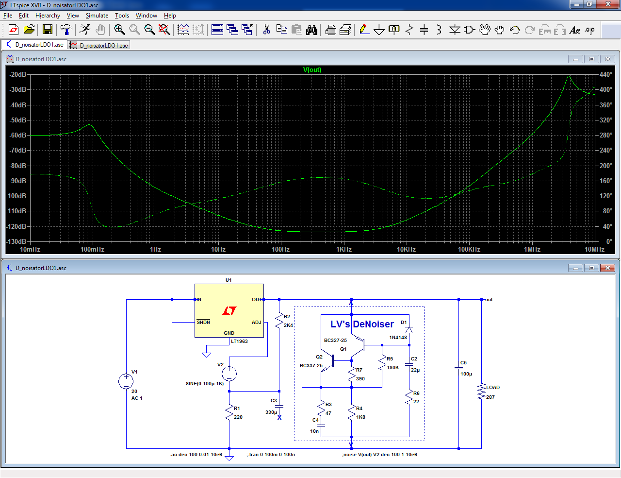
Note that this is the topology, and is purely theoretical: there is no guarantee it will actually work (= be stable) in reality.
In particular, R3 and C4 might need to be adapted: in the sim, with a LT1963 they look quite critical.
With other regulators, not present in the LTspice library, a real world test (and probably tweak) will be required.
Other regulators generally have a higher impedance feedback divider (R1, R2).
It is therefore not necessary to use low value resistors in the amplifier (R4, R5).
The resistors can be scaled according to the equivalent resistance of the FB divider.
This in turns allows lower values for C2 and C3. With lower, more convenient values, the ratio of C3 to C2 can be increased to reduce the slight VLF peaking.
All of this is completely speculative, and needs to be checked and refined in reality.
It is quite possible that some regulators will not work at all with a Die/denoiser!
The resistor R7 will need to be optimized according to the output voltage (and the scaling).
Diego has provided a table for R7 (with R4=1K8):
D-Noizator: a magic active noise canceller to retrofit & upgrade any 317-based V.Reg.
Attachments


Elvee, in your opinion, does the denoiser's performance swamp out the differences between regulator input capacitor values? In other words, will you have just as clean power supply with a 2200 µF cap before the regulator as with a 15,000 µF one? This is, of course, assuming that the cap is big enough to not let the regulator fall out of its zone.
Last edited:
Hello
I will make a few PCBs and test multiple LDOs based on above. After testing I will post the results here
I will make a few PCBs and test multiple LDOs based on above. After testing I will post the results here
No, massive amounts of brute force work, thus the input 100/120Hz ripple will be reduced ~100dB by the denoiser, and if the input ripple is 15000/2200 times smaller, the output ripple will be reduced in the same proportion.
The improvement might not be detectable if the ripple is drowned in noise.
Before increasing the cap to insane values, you should estimate quantitatively what level you actually need, and opt for the resulting value with a good safety margin
The improvement might not be detectable if the ripple is drowned in noise.
Before increasing the cap to insane values, you should estimate quantitatively what level you actually need, and opt for the resulting value with a good safety margin
Edit:
I now belatedly realize that I have forgotten to move the compensation cap to the other side.
This is the corrected version:
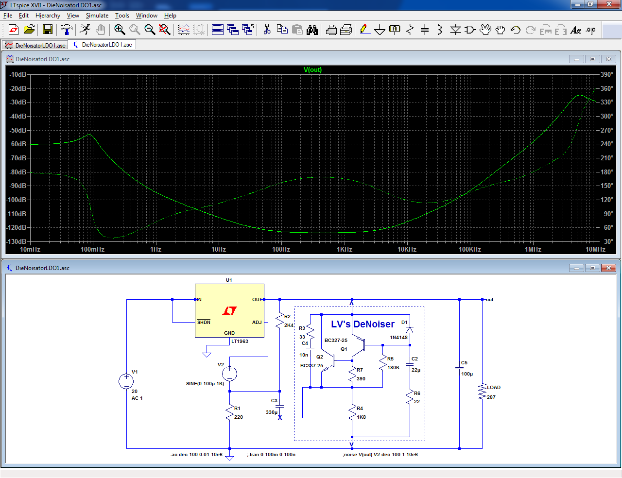
The wrong circuit has been on line for ~9 months now, I just hope that nobody went mad trying to have it working...
Maybe because the first results were poor because of the wrong circuit, and because the maximum input voltage was 20v (when I needed 35v at least), I didn't care so much for the LT1963 and tested only PSRR.
With the corrected circuit, sims for PSRR, noise and impedance now look very very interesting.
But as you say: now it needs an actual field test, to see if it's up to the sims.
Then there's also the practical availability of LT1963 power supplies at reasonable prices to add the Denoiser to.
So I do not expect to see many projects involving LT1963 + Denoiser around.
Edit:
I now belatedly realize that I have forgotten to move the compensation cap to the other side.
This is the corrected version:
The wrong circuit has been on line for ~9 months now, I just hope that nobody went mad trying to have it working...
I built the first circuit and it works like a charm. Without the compensation capacitor it oscillates, with it, it doesn't.
In you latest schematic, much more than just the compensation cap has shifted position. I am somewhat puzzled.
- Home
- Amplifiers
- Power Supplies
- D-Noizator: a magic active noise canceller to retrofit & upgrade any 317-based VReg