
Best regards
Interestingly I completely missed your post Diego. I found it interesting and I started playing with it, and naturally I came to this version:
Performance is incredibly good, even better! than the NoNoizator variant I made with CCS. Not much but it's there, especially at LF.
There's always 1.25V across the CCS, which makes it work fine, and also I get this better performance at half the denoiser circuit current!
I have good performance with even lower current, but noise starts to increase a bit. I think 200R is a good compromise for a total of around 6-7mA (LED current included!) total draw from the denoising circuit.
So we remove a BJT, a diode, few resistors and also that large coupling capacitor! More than this, the startup swing isn't there. It just slowly starts.
It does take a while to get to nominal Vout, 2-3 minutes, but there's no more overshoot.
Vout is set by R32 in the last photo, and phase seems similar to the NoNoisator version, apart from LF.
I find it really interesting, more performance for less parts, stability should (!) be similar, and there's no more overshoot.
I guess this is a DC-coupled denoiser?
Also I'm clearly building a board to measure this circuit, I'm really curious. I attached a LTSpice sim file with both NoNoisator and this version, for both high and low gains for both 12Vout and 5Vout. PSRR seems a tad better, noise a tad worse due to lower current in the denoising circuit, output impedance is a tad better.
Ah yes, I also have control over the PSRR peak and I can place it around 100Hz by adjusting R34 from LED, R33 for current in denoising circuit, and C26 sense cap value. But I have to measure this, I'm just going by the simulation at this point.
As it stands I still find the lower gain version interesting, very good performance for least parts.
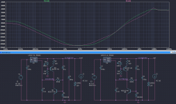
Here's a PSRR comparison between the CCS NoNoisator and this latest version:
And another between the two gain versions of this latest circuit:
edit: also in this circuit the CCS BJT seems to matter now, and it "likes" high gain ones. BC560C seems to also work good in that spot.
2nd edit: actually the latest PCB design allows for this configuration. Just omit the respective parts and close JP8 jumper, and I guess short the coupling cap.
Attachments
Last edited:

I got a chance to measure this circuit and it's quite interesting. Has a different behavior than the previous ones.
First of all, this completely messes with the output DC point setting so if anything goes wrong with the denoising circuit you'll have a pretty bad time as you'll most likely have Vin-1.25V on Vout.
So with that out of the way:

R2 basically sets the output noisefloor. 100R makes for around 250nV and 220R makes for around 350nV total (BC3x7).
But increasing the current with R2=100R makes for a bit worse PSRR. This is different from the previous circuits.
LED current seems to also affect PSRR, the lower current through the LED the higher the PSRR.
Turn-on time seems tied to R1 value. The higher this value the longer the startup time. To lower this value for same Vout means you have to increase LED current and also lower R2, which in turn affects PSRR.
At least this is what I'm getting out of it so far.
PSRR seems to vary quite a bit depending on these conditions. I can get it between 135dB and more than 150dB at 100Hz, but I'm not yet sure, just some of my observations so far.
MPSAx6 pair didn't give me good PSRR results so far. Yet to try the ZTXx51 pair.
Ah yes, also it seems pretty stable, and recovers very fast if I poke at the denoiser innards. I may try the higher gain version but I don't think it will be necessary. PSRR seems to be pretty high as it is.
First of all, this completely messes with the output DC point setting so if anything goes wrong with the denoising circuit you'll have a pretty bad time as you'll most likely have Vin-1.25V on Vout.
So with that out of the way:
R2 basically sets the output noisefloor. 100R makes for around 250nV and 220R makes for around 350nV total (BC3x7).
But increasing the current with R2=100R makes for a bit worse PSRR. This is different from the previous circuits.
LED current seems to also affect PSRR, the lower current through the LED the higher the PSRR.
Turn-on time seems tied to R1 value. The higher this value the longer the startup time. To lower this value for same Vout means you have to increase LED current and also lower R2, which in turn affects PSRR.
At least this is what I'm getting out of it so far.
PSRR seems to vary quite a bit depending on these conditions. I can get it between 135dB and more than 150dB at 100Hz, but I'm not yet sure, just some of my observations so far.
MPSAx6 pair didn't give me good PSRR results so far. Yet to try the ZTXx51 pair.
Ah yes, also it seems pretty stable, and recovers very fast if I poke at the denoiser innards. I may try the higher gain version but I don't think it will be necessary. PSRR seems to be pretty high as it is.
Finished testing this circuit. I think it is by far the best iteration.
I measured with about 15Vin and 12Vout, 150R load. I measured right at the output connector where the denoiser is also sensing. For 5Vout I used a 50R load.
I measured both regular LM3x7, TI's LM3x7-N and LM338. Overall LM3x7-N showed 4-5dB more PSRR than regular LM317, LM338 was pretty similar to the regular LM317. Noise was the same on all, there doesn't seem to be many differences in this aspect.
Ferrite bead isn't needed anymore, actually ruins PSRR performance.
One interesting thing I discovered is that the compensation network has way too high values for this configuration. Seems stable without the resistor on both positive and negative versions, and capacitor I could lower to 1nF and still have the circuit stable. Lowering the capacitor value from 30nF to 4.7nF seemed to lower the total noise from around 250nV to under 100nV for both positive/negative and seems somewhat regulator agnostic. I settled for 2.2nF for the measurements, no resistor.
For BJTs I recommend the BC3x7-40 pair. Tried MPSAx6 and while they have a tad lower noise, they have worse PSRR performance, but not by much. ZTXx51 does have lower noise but I'm not sure it matters at this level, it's something like 70nV vs 85nV. They're good, just that it doesn't really make sense considering their price. But you can use them if you want.
Startup doesn't take that long, for 12Vout in 10-15 seconds the output is already at around 10V. There's no overshoot, it just slowly builds up to nominal Vout. For 5Vout it's even faster.
The only thing you change between 5Vout and 12Vout is the Vout resistor value, LED resistor you keep at 20-22k.
I used the output capacitors that I used in previous designs and seems to work fine.
I tried poking with metal tweezers at ADJ pin and different parts of the circuit and it seems to recover very fast. I saw no DC change while poking. This was valid for all tested regulators.
I measured PSRR at 70Hz/105Hz/440Hz/1kHz/5kHz/15kHz.
LM317-N (12Vout)
70Hz - 143.7dB
105Hz - 144.1dB
440Hz - 144.2dB
1kHz - 142.2dB
5kHz - 125.6dB
15kHz - 108.7dB
5Vout is similar, not much difference between different Vout.
LM337-N (12Vout)
70Hz - 133.7dB
105Hz - 132.9dB
440Hz - 125.1dB
1kHz - 118.2dB
5kHz - 104.5dB
15kHz - 95.9dB
Noise is at around 100nV measured, and my LNA has around 62nV of noise, so around 80nV for both LM3x7-N/regular LM3x7/LM338.
Noise with ZTXx51 was around 83nV measured, so around 55nV for just the regulator. Very low, but BC3x7 is still good enough.
I have attached the measurements and LTSpice sim with recommend values for 12Vout, for both negative and positive.
Tomorrow I'll post the pcb files for the board I measured.
Attachments
Yes, I think Vout will differ between same model BJTs.
I played with tempco in simulation and I am getting good results with MPSA06 in denoiser spot. SS8050 simulates well in this regard as well. But I don't know if this is due to a simpler LTSpice models (just a guess) or other factors.
I played with tempco in simulation and I am getting good results with MPSA06 in denoiser spot. SS8050 simulates well in this regard as well. But I don't know if this is due to a simpler LTSpice models (just a guess) or other factors.
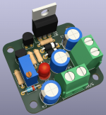
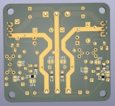
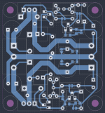
This post is about the PCB designs for this circuit.
I've made the single LM317 version (which I measured), single LM337 version which is basically identical to the LM317 version just that input/output traces for regulator differ.
There's also a dual version which I have not tested, so you do that at your own risk.
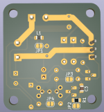
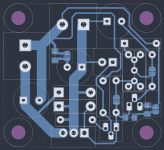
Since the circuit simplified the PCBs also got smaller. Single versions are around 35mm X 38mm and dual is 50mm X 46mm. All have output traces exposed so you can fill them with solder to decrease resistance. I especially recommend that if you plan on using LM338 at full output current.
There's no more remote sensing, it's done at the output connector for predictable results. But the circuit supports sensing at the load, if you want to integrate it into something else.
All three boards are single sided, DIY-able and don't have any topside passes.
Capacitor footprints are 8mm and should allow for max Vout of the regulators. You should be able to find the 47uF sensing cap in 8mm diameter with 50V rating.
Input capacitor has to be at least 10uF but you can also find 100uF/50V in 8mm diameter.
For output capacitor for LM317 I used Panasonic FC 100uF/63V 8mm diameter version (EEUFC1J101L).
For LM337 I used a Panasonic FR 470uF/25V 8mm diameter version (EEUFR1E471L) but 150uF/63V 8mm diameter version should also work (EEUFR1J151L).
I have not tested more than 12Vout and more than 100mA so there might be surprises at higher voltages/currents. At 30Vout you need to take into consideration the heat from the denoiser BJT, it's around 0.25W.
LED should be a regular 5mm red LED.
Make sure you populate all protection diodes.
For setting Vout there's a regular resistor in series with the potentiometer. You can bypass it with a SMD jumper if you wish to only use a potentiometer. There's also two regular resistors in parallel with the potentiometer, on the same footprint as the potentiometer. You can use either/or for flexibility.

Output caps have a 0805 footprint in series to GND, you can also bypass this with a SMD jumper. I left it there just to have options later down the line if anything comes up regarding output capacitor RLC network. So normally do not populate L1/L2 and close the jumpers.
Same thing for the R in compensation network. Do not populate it and close the SMD jumper.
There's a protection resistor footprint in series with the sensing cap. This affects the performance of the circuit and I have not tested with it in circuit. But if you want its protection then you should install it. 22R to 47R but maybe others can chime in on this. You can bypass it by soldering the SMD jumper under it.
For BJTs use BC337-40/BC327-40, they work very good and are accessible. Use the high gain -40 version for both. I may test with others when I have some time.
CCS BJT you could keep BC327-40 while testing other denoiser BJTs. Tried MPSA56 here and PSRR performance was a bit worse overall. Swapping this CCS BJT does not affect Vout much. Swapping the deoniser BJT drastically changes Vout depending on BJT.
For example using a MPSA06 for denoiser BJT requires around 280K for 12Vout, while BC337-40 requires around 550K for 12Vout. But MPSA06 is still a good choice, a bit lower noise even, and needing an almost twice as low resistor that makes for a faster startup time.
CCS resistor should be 100R for around 8-9mA.
LED resistor should be 20K-22K. This seemed fine even for 5Vout.
Normally with LM317 there's a loop formed between Vout and ADJ with the R1 (120R-240R) resistor.
That loop is now formed with CCS 100R resistor and CCS BJT, so I tried to keep that loop as small as possible.
I again insist that this circuit alters the way LM317 datasheet sets Vout. With the previous AC coupled denoiser circuits if they weren't stable at worst Vout would oscillate between GND and set Vout. But with this latest circuit Vout is set by the denoiser circuit, and if that's not stable your output will swing between GND and Vin-1.25V. Do not use it to power something important/valuable before making sure it's stable.
I don't yet see a need to add the extra dienoiser complication as the performance is pretty good as it is. More than likely that circuit will be unstable and would require some extra testing that I don't yet have time for. Maybe at some point I'll look into it.
At one point I did manage to get over 160dB of PSRR at 100Hz with this simpler circuit but I don't remember which BJTs/other values I used. I will test some more when I find the time.
I attached Kicad project files, includes gerbers, pdf schematics and DIY pdf.
I release all files related to this circuit under Attribution-NonCommercial-ShareAlike CC BY-NC-SA license.
edit: to set Vout it's best to remove the sensing capacitor from the PCB, set Vout then solder it back in. Without it the supply starts fast. With it in circuit it's a bit of a pain to set Vout.
I've made the single LM317 version (which I measured), single LM337 version which is basically identical to the LM317 version just that input/output traces for regulator differ.
There's also a dual version which I have not tested, so you do that at your own risk.
Since the circuit simplified the PCBs also got smaller. Single versions are around 35mm X 38mm and dual is 50mm X 46mm. All have output traces exposed so you can fill them with solder to decrease resistance. I especially recommend that if you plan on using LM338 at full output current.
There's no more remote sensing, it's done at the output connector for predictable results. But the circuit supports sensing at the load, if you want to integrate it into something else.
All three boards are single sided, DIY-able and don't have any topside passes.
Capacitor footprints are 8mm and should allow for max Vout of the regulators. You should be able to find the 47uF sensing cap in 8mm diameter with 50V rating.
Input capacitor has to be at least 10uF but you can also find 100uF/50V in 8mm diameter.
For output capacitor for LM317 I used Panasonic FC 100uF/63V 8mm diameter version (EEUFC1J101L).
For LM337 I used a Panasonic FR 470uF/25V 8mm diameter version (EEUFR1E471L) but 150uF/63V 8mm diameter version should also work (EEUFR1J151L).
I have not tested more than 12Vout and more than 100mA so there might be surprises at higher voltages/currents. At 30Vout you need to take into consideration the heat from the denoiser BJT, it's around 0.25W.
LED should be a regular 5mm red LED.
Make sure you populate all protection diodes.
For setting Vout there's a regular resistor in series with the potentiometer. You can bypass it with a SMD jumper if you wish to only use a potentiometer. There's also two regular resistors in parallel with the potentiometer, on the same footprint as the potentiometer. You can use either/or for flexibility.
Output caps have a 0805 footprint in series to GND, you can also bypass this with a SMD jumper. I left it there just to have options later down the line if anything comes up regarding output capacitor RLC network. So normally do not populate L1/L2 and close the jumpers.
Same thing for the R in compensation network. Do not populate it and close the SMD jumper.
There's a protection resistor footprint in series with the sensing cap. This affects the performance of the circuit and I have not tested with it in circuit. But if you want its protection then you should install it. 22R to 47R but maybe others can chime in on this. You can bypass it by soldering the SMD jumper under it.
For BJTs use BC337-40/BC327-40, they work very good and are accessible. Use the high gain -40 version for both. I may test with others when I have some time.
CCS BJT you could keep BC327-40 while testing other denoiser BJTs. Tried MPSA56 here and PSRR performance was a bit worse overall. Swapping this CCS BJT does not affect Vout much. Swapping the deoniser BJT drastically changes Vout depending on BJT.
For example using a MPSA06 for denoiser BJT requires around 280K for 12Vout, while BC337-40 requires around 550K for 12Vout. But MPSA06 is still a good choice, a bit lower noise even, and needing an almost twice as low resistor that makes for a faster startup time.
CCS resistor should be 100R for around 8-9mA.
LED resistor should be 20K-22K. This seemed fine even for 5Vout.
Normally with LM317 there's a loop formed between Vout and ADJ with the R1 (120R-240R) resistor.
That loop is now formed with CCS 100R resistor and CCS BJT, so I tried to keep that loop as small as possible.
I again insist that this circuit alters the way LM317 datasheet sets Vout. With the previous AC coupled denoiser circuits if they weren't stable at worst Vout would oscillate between GND and set Vout. But with this latest circuit Vout is set by the denoiser circuit, and if that's not stable your output will swing between GND and Vin-1.25V. Do not use it to power something important/valuable before making sure it's stable.
I don't yet see a need to add the extra dienoiser complication as the performance is pretty good as it is. More than likely that circuit will be unstable and would require some extra testing that I don't yet have time for. Maybe at some point I'll look into it.
At one point I did manage to get over 160dB of PSRR at 100Hz with this simpler circuit but I don't remember which BJTs/other values I used. I will test some more when I find the time.
I attached Kicad project files, includes gerbers, pdf schematics and DIY pdf.
I release all files related to this circuit under Attribution-NonCommercial-ShareAlike CC BY-NC-SA license.
edit: to set Vout it's best to remove the sensing capacitor from the PCB, set Vout then solder it back in. Without it the supply starts fast. With it in circuit it's a bit of a pain to set Vout.
Attachments
-
 Screenshot_20220721_065817.png143.9 KB · Views: 212
 -
 Screenshot_20220721_065955.png163.8 KB · Views: 211
 -
 Screenshot_20220721_070043.png138.2 KB · Views: 221
 -
 Screenshot_20220721_065210.png145.5 KB · Views: 226
 -
 Screenshot_20220721_065346.png167.4 KB · Views: 211
 -
 Screenshot_20220721_065456.png79.4 KB · Views: 174
 -
LM317.zip209.2 KB · Views: 183
-
LM337.zip160.7 KB · Views: 123
-
dual.zip252.1 KB · Views: 177
Last edited:
@Trileru
These values are really impressive.😮
I don't have the equipment to measure this low PSSR,
(I use a low-impedance headphone coupled with a capacitor and try to hear something) 🤭
🤭
so... allow me to ask you.
Would it be a good idea to couple the "Dienoiser" to a simple capacitance multiplier? Or.. Does the LM317 easily outperform in PSSR and general any simple capacitance multiplier? 🤔
Best Regards.
These values are really impressive.😮
I don't have the equipment to measure this low PSSR,
(I use a low-impedance headphone coupled with a capacitor and try to hear something)
🤭so... allow me to ask you.
Would it be a good idea to couple the "Dienoiser" to a simple capacitance multiplier? Or.. Does the LM317 easily outperform in PSSR and general any simple capacitance multiplier? 🤔
Best Regards.
Negative feedback voltage regulators almost always (99% of cases) have much better PSRR than non-feedback capacitance multipliers. Yes that includes the Sziklai type of capacitance multiplier too; NFB VREGs have much better PSRR.
Of course super clever people can exhibit counterexamples of terrible NFB voltage regulators that are inferior to capacitance multipliers. But a well designed voltage regulator having LOTS of negative feedback (like Jung/Didden) wins the race every time. ESPECIALLY at subharmonics of the AC mains (6.25, 12.5 , 25 Hz) and/or (7.5 , 15 , 30 Hz)
Of course super clever people can exhibit counterexamples of terrible NFB voltage regulators that are inferior to capacitance multipliers. But a well designed voltage regulator having LOTS of negative feedback (like Jung/Didden) wins the race every time. ESPECIALLY at subharmonics of the AC mains (6.25, 12.5 , 25 Hz) and/or (7.5 , 15 , 30 Hz)
Last edited:
Thank you for your answer.Negative feedback voltage regulators almost always (99% of cases) have much better PSRR than non-feedback capacitance multipliers. Yes that includes the Sziklai type of capacitance multiplier too; NFB VREGs have much better PSRR.
Of course super clever people can exhibit counterexamples of terrible NFB voltage regulators that are inferior to capacitance multipliers. But a well designed voltage regulator having LOTS of negative feedback (like Jung/Didden) wins the race every time. ESPECIALLY at subharmonics of the AC mains (6.25, 12.5 , 25 Hz) and/or (7.5 , 15 , 30 Hz)
Maybe I didn't express it correctly.
I always see something related to this old topology being used. (attached image)
A simple capacitance multiplier with single feedback and a zener reference.
The question would be: Does a (very cheap) LM317 IC perform better? Why?
Attachments
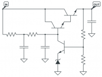
That's called a voltage regulator: it has a reference, a feedback loop, etc.A simple capacitance multiplier with single feedback and a zener reference
Such a basic circuit will be outperformed by any monolithic regulator, even a LM317.
It is possible to make discrete regulators vastly superior than most integrated ones: Trileru and I have given examples of such regulators on this forum.
Combining a (true) capacitance multiplier with a 317 is possible, but you need to think about what you want to achieve: if you place the cap-mult upstream, you will improve the PSRR but not the noise, and the opposite will improve everything except the output impedance, which will be ruined.
All of this has already been discussed in this thread, and the best possible option is to use a cap-mult followed by a denoiser-equipped 317. This will result in stellar performances, but will cost several volts of dropout
Indeed: it is difficult to beat passives for cost/performances at HF. You can always design very good HF active circuits, but it is complicated, costly, and beyond UHF frequencies it becomes almost insurmountable.
A simple inductor + ceramic capacitor costs pennies, and achieves the same kind of performance if the layout is up to the task (very important!).
Something to keep in mind with LC filters is unwanted resonances: a LC lowpass will present a huge impedance peak at the resonant frequency, and it has to be mitigated in some way.
That said, a regular voltage regulator tends to behave as a gyrator due to the feedback loop, and it will also resonate with a low-losses capacitor connected to its output
View attachment 1076795
Try this very simple circuit.
I had thought about it a while ago.
Best regards
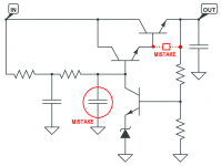
Safer circuit for adjusting output voltages:
Trying to solve the high initial swing I tried this addition which seems to somewhat help. It affects the PSRR by 2-3dB max, rest seems it doesn't do much, apart from having a nicer startup. It connects the denoising circuit output after 20 seconds or so.

Seems to work fine for 5Vout as well:

Seems to work fine for 5Vout as well:
Wouldn't a small series R solve that?Something to keep in mind with LC filters is unwanted resonances: a LC lowpass will present a huge impedance peak at the resonant frequency, and it has to be mitigated in some way.
Tempco seems pretty bad.Safer circuit for adjusting output voltages:

Attachments
Last edited:
Tempco seems pretty bad.
Yes, that is its weak point, although it has the advantage of not having an overshoot when turned on, which could be beneficial for sensitive circuits.
- Home
- Amplifiers
- Power Supplies
- D-Noizator: a magic active noise canceller to retrofit & upgrade any 317-based V.Reg.