D-Noizator: a magic active noise canceller to retrofit & upgrade any 317-based V.Reg.
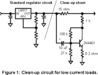
From Wenzel finesse regulator: Finesse Voltage Regulator Noise! |
Drawbacks are obvious:
a) Low current
b) Affects static and dynamic operation
c) Limited correction ability
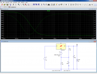
Let us start with the basic regulator (including the additional bypass cap, since we strive for the lowest noise).
An additional source symbolizing the noise is shown explicitly.
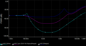
The bypass cap is effective down to ~10Hz, but the level does not fall below 0dB.
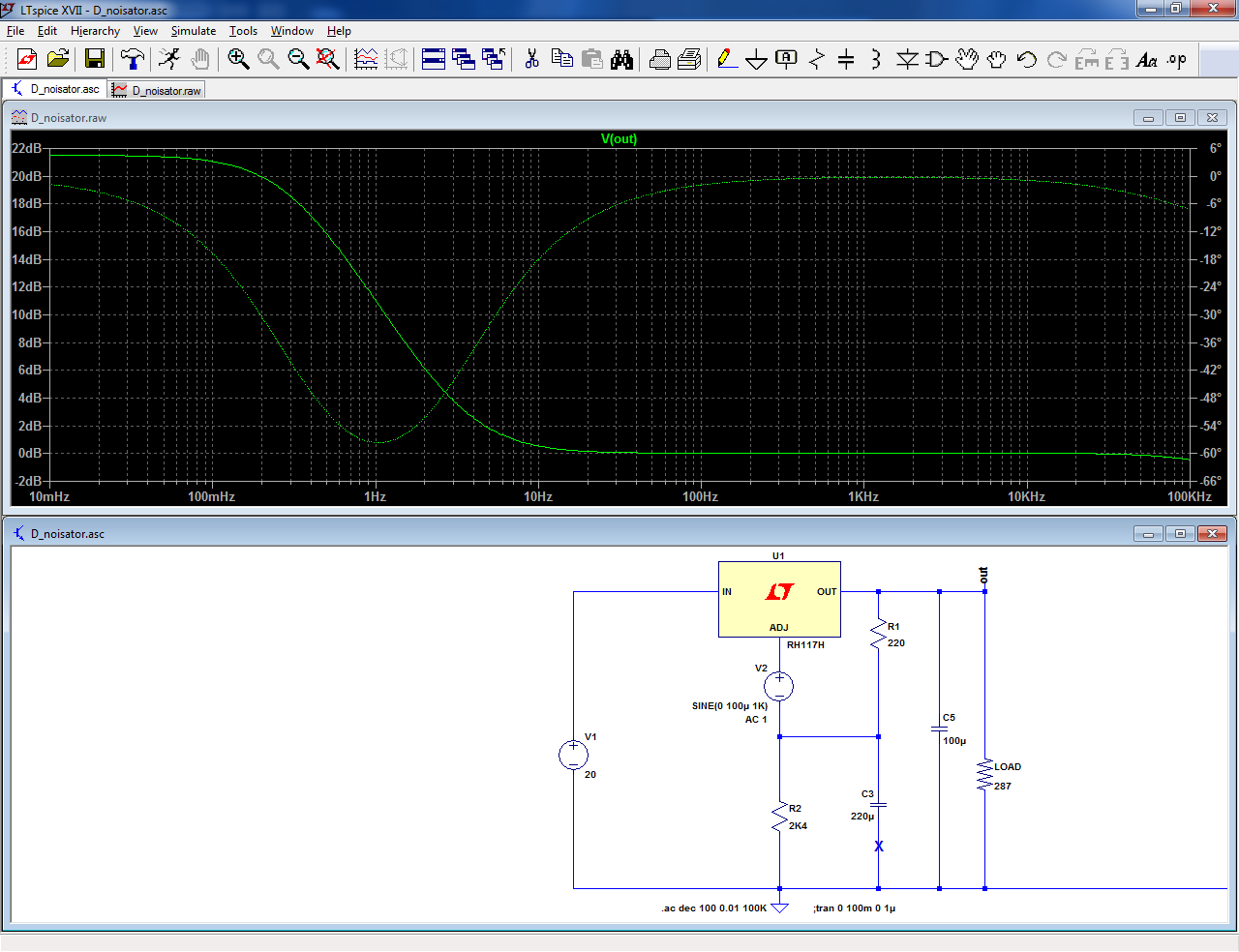
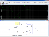
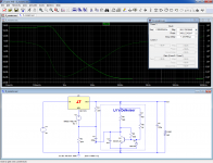
Now, let us add the D-Noizator piggy-back:
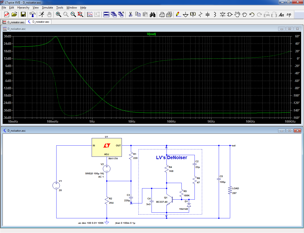
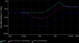
The floor drops by more than 30dB.
The circuit works by changing the output node into an AC virtual ground.
Therefore, benefits do not stop at internal noise reduction: all the performances benefit: PSRR, output impedance.
Ultimately, the performances are limited by the discrete transistor.
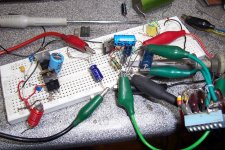
What about the reality?
I made a test with ST and ONsemi samples. They behave as perfect clones, both with and without the D-Noizator.
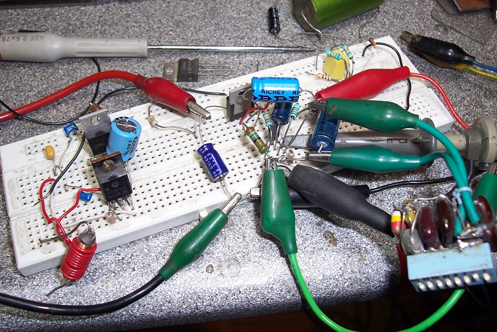
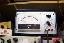
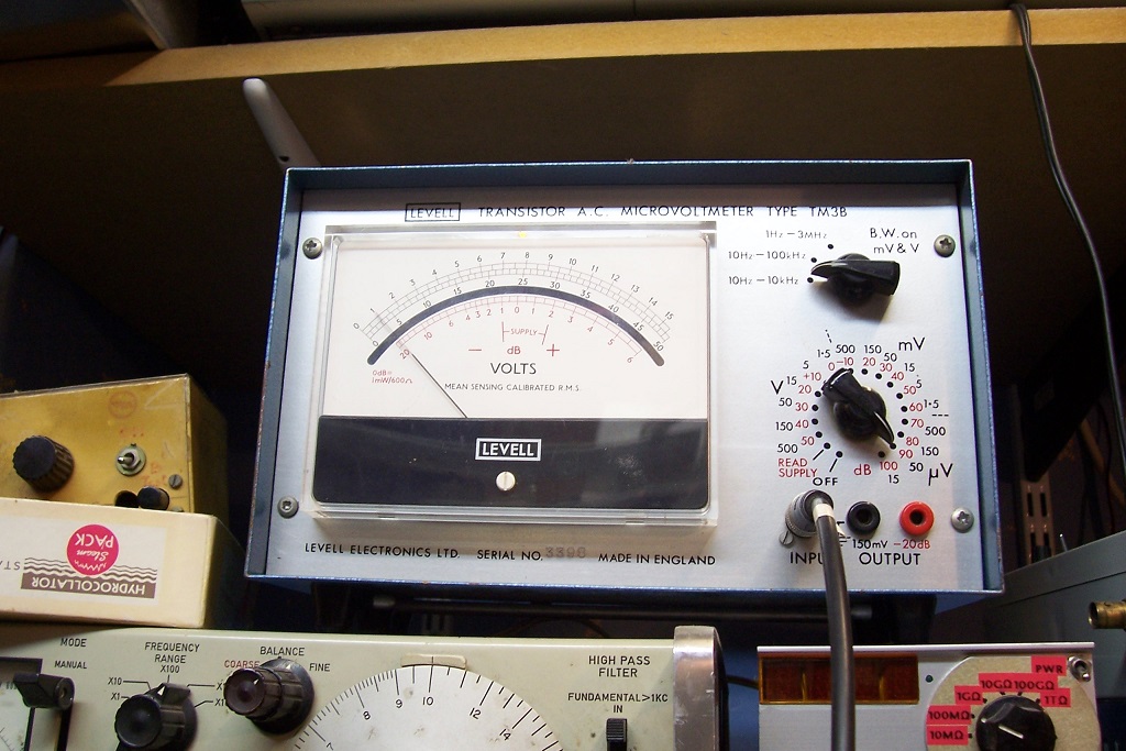
With just the cap, the noise is 16μV, as measured by a Levell TM3B.
With the D-Noizator, it falls to 2.5μV~3μV, which seems to indicate that the circuit doesnt deliver all of the promised improvement... except that the noise floor of the TM3 is also 2.5μV~3μV.
The TM3 is not a bad instrument, but it is very cheap, and very dated.
I would need to add a modern LNA to make meaningful measurements.
It is more than promising, anyway.
Of course you cannot throw a large gain into the regulator's loop without consequences: it is now forced to operate at a gain much lower than unity, and without precautions, it oscillates like mad, which comes as no surprise.
However, compensation seems to be easily achieved, and very tolerant: a capacitor larger than 2nF was sufficient to stop oscillations.
A VLF peaking is visible in the response; it could probably be polished off by increasing the splitting of the poles, or similar measures
Detailed index:
Since the thread contains lots of information about various versions, sub-versions, practical implementations, etc. I have decided to gather here all of the most useful links, to help would-be builders chose the best solution for their application.
Miscellaneous:
✪ A simple circuit that transforms a good, clumsy workhorse like the LM317 into a superreg so easily that you do not even need to cut a single track. ✪
✪ It must be too good to be true.... or ✪
 .........................................................................................................................
 It's Christmas!!!


The present SOTA in VR noise cancellation is this:✪ It must be too good to be true.... or ✪
 .........................................................................................................................
 It's Christmas!!!


From Wenzel finesse regulator: Finesse Voltage Regulator Noise! |
Drawbacks are obvious:
a) Low current
b) Affects static and dynamic operation
c) Limited correction ability
Let us start with the basic regulator (including the additional bypass cap, since we strive for the lowest noise).
An additional source symbolizing the noise is shown explicitly.
The bypass cap is effective down to ~10Hz, but the level does not fall below 0dB.
Now, let us add the D-Noizator piggy-back:
The floor drops by more than 30dB.
The circuit works by changing the output node into an AC virtual ground.
Therefore, benefits do not stop at internal noise reduction: all the performances benefit: PSRR, output impedance.
Ultimately, the performances are limited by the discrete transistor.
What about the reality?
I made a test with ST and ONsemi samples. They behave as perfect clones, both with and without the D-Noizator.
With just the cap, the noise is 16μV, as measured by a Levell TM3B.
With the D-Noizator, it falls to 2.5μV~3μV, which seems to indicate that the circuit doesnt deliver all of the promised improvement... except that the noise floor of the TM3 is also 2.5μV~3μV.
The TM3 is not a bad instrument, but it is very cheap, and very dated.
I would need to add a modern LNA to make meaningful measurements.
It is more than promising, anyway.
Of course you cannot throw a large gain into the regulator's loop without consequences: it is now forced to operate at a gain much lower than unity, and without precautions, it oscillates like mad, which comes as no surprise.
However, compensation seems to be easily achieved, and very tolerant: a capacitor larger than 2nF was sufficient to stop oscillations.
A VLF peaking is visible in the response; it could probably be polished off by increasing the splitting of the poles, or similar measures
This post details the possible versions, and provides practical information:
D-Noizator: a magic active noise canceller to retrofit & upgrade any 317-based V.Reg.
D-Noizator: a magic active noise canceller to retrofit & upgrade any 317-based V.Reg.
Detailed index:
Since the thread contains lots of information about various versions, sub-versions, practical implementations, etc. I have decided to gather here all of the most useful links, to help would-be builders chose the best solution for their application.
- First, the recommended implementations for the basic denoiser and nonoiser, here
- Jack's PCB for the nonoiser in pdf form
- Sadface's Gerbers
- Hicoco's Gerbers
- Tombo56's Gerbers (tested later in the thread) and their updated versions, + negative one, and a minor correction , and BOM
- Mark's VRDN project
- A complete project, including the AC section from Iamwhoiam
- Knauf1919's Gerbers
- Seeyou's implementation of a VRDN clone
- First, the denoiser with add-on CCS boards
- The nonoiser add-on boards
- Full size DC supply for AC-coupled Nonoiser with CCS (and lower performance variants possible)
- And the DC-coupled Denoisator with CCS
- An explanatory text by Trileru, detailing his versions of X-noisers
- Components selection guide for Trileru's designs
- Measurements on a regular nonoiser
- Some stress-testing by Tombo56
- Transient response by Tombo56
Miscellaneous:
- Accurate formula to determine the exact output voltage of the nonoiser,
- Clarification of the Kelvin connections
- Dienoiser used with 78xx regulators
- Another application of a denoiser-like circuit to 78xx
- A tentative (in sim) to apply the denoiser to a TL431, by Tombo56
Attachments
Last edited:
It depends on two things: is the target supply using a divider for the voltage setting, and can you find a discrete transistor better than the regulator's internal circuitry? Note that even a fixed regulator could benefit from the fix, but from a practical POV, things would be much more difficult: you would need to isolate the reference terminal, which generally happens to be GND. Probably a detail for compulsive modders, but a serious obstacle for all the others.Wonder how well it will work for digital stuff like DAC supplies.
In principle, you will always be able to find a discrete superior to the internal circuits of a VR, but with modern VR's, this is going to be difficult, and perhaps not worth the trouble. With 317 style regulators, it was easy, because the IC has to cope with everything, DC, AC, thermal stability at the same time. With a discrete, you can separate the AC and DC paths, which eases matters considerably. However, IC designs have become so much smarter that bettering them requires a significant effort. It is certainly possible, but any gain is probably going to be marginal, and if you want a real improvement, you need to design everything from scratch, not try to improve on something that is barely improvable
Nice circuit, like in all threads that you start!
I have been able to refine the measurements: I remembered that one channel of one of my lab amplifiers is equipped with a OPA27.
This brought the noise floor of my test set-up to 0.75µV.
When measuring the D-noizator, I got 1.0µV.
This means that the actual noise is in the vicinity of 0.66µV.
Since the noise with the cap connected normally is still 16µV, the improvement ratio is 27.7dB, much closer to what the sim predicted.
Of course, the test is made on a breadboard, and the transistor is just an ordinary BC337-40 from Philips.
With a good PCB and a super low noise transistor, it would be possible to scrape a few tens of nV
Summary: low noise voltage regulator achieved using twelve electronic components, one of which is an integrated circuit.
Summary: low noise voltage regulator achieved using twelve electronic components, one of which is an integrated circuit.
You forgot "magic".
Yes.Summary: low noise voltage regulator achieved using twelve electronic components, one of which is an integrated circuit.
The piggyback alone (since the main use of this circuit is probably going to be the retrofitting existing regulators) requires 7 components
Yes, of course: use a PNP and reverse the polarity of E-caps.Would the same principle apply for the LM337?
Here is a slightly better tradeoff: the current consumption is increased, but the improvement factor is 38dB, and the VLF peak is mostly gone.
Going further probably makes little sense, since finding a transistor sufficiently good to capitalize on the gain is going to be difficult.
Attachments
This is just an add-on, but I would love to see a superreg in its own right using <12 components, of which none is an IC.Summary: low noise voltage regulator achieved using twelve electronic components, one of which is an integrated circuit.
The current season is certainly the right time for such a development....
Is someone up to the task?
v
v
v
v

v
v
v

I would love to see a low noise voltage regulator using twelve or fewer electronic components, and I don't care how many or how few of them are ICs. If one IC is allowed, seven are also allowed.
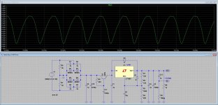
If low frequency steady state power supply rejection is your primary concern, you can cascade regulators. This is one of the options I considered (and rejected) for the heaters of the preamp I'm currently working on: a cap multiplier as a pre-filter for the regulator. Sim yields 1.3uVpp@100Hz, but it doesn't account for the random noise of the regulator itself.
Attachments
Why no Zener diode at the base of Q1? It will increase mains ripple rejection ("PSRR at low frequencies") by many decibels.
Why no Zener diode at the base of Q1? It will increase mains ripple rejection ("PSRR at low frequencies") by many decibels.
For no particular reason, it's just a proof of concept. But you got me curious, so here it goes: no change, even after I force double precision.
The explanation: the 1000uF cap is worth about 1.6 ohms at 100Hz, whereas the Zener typically is 7-15 ohms, so it's not very effective in this case.
Attachments
Thanks Elvee.
The "Finesse" circuit works OK (and it can be adjusted)
Performance measurements are here (page 2, 3)
https://www.edn.com/electronics-blo.../Simple-circuits-reduce-regulator-noise-floor
And a strong enough noise source (for testing)
https://www.edn.com/design/analog/4420926/White-noise-source-flat-from-1Hz-to-100kHz
George
Attachments
Yes Maxim application note 3657 looks like it contains some good ideas. Pair it with a 36V supply, RRIO opamp like LT1498 and you can use the Walt Jung trick of connecting the opamp's power supply input pin, to the final regulator's output. With a RRIO opamp you don't need Walt's level shifter. Be sure to filter the holy heck out of the reference voltage (Maxim R1 and C1), I've used 3 terminal "feedthru" capacitors for this purpose. Such as YFF31AH2A105MT0Y0N.
OMG. A LT3042 with an external transistor to carry the dissipation is
> 40 dB better than any LM317, right from the start.
Circuit is in the data sheet.
There is no point to mess with the LM317's loop gain.
Oh, yes, it's tested:
< Lt3042_DH44 | Low noise regulator consisting of LT3042 and D… | Flickr >
< spectrum_lt3042_DH44 | Noise spectrum of the LT3042+ D44VH10… | Flickr >
And Wenzel's finesse thing cannot be tuned, it NEEDS to be tuned
for optimum results.
cheers & happy winter solstice
Gerhard
cheers & happy winter solstice
Gerhard
The days are getting longer.
The easy to characterize parameters for a super-reg:
1) PSRR
2) Noise
3) Z out
The (somewhat) harder to characterize parameter:
4) THD
The error amplifier can't be damped as it will impinge back on the rails part of the problem it just saw. Yet, the error amplifier has to be stable. * This is what one of the respondents to the Linear Audio article commented, and the bit of analysis I did, correlating FFT with the perceived results, seemed to bear it out. Unfortunately, or fortunately, Jan has better things to do with his time and there doesn't seem to be an interest in further research.
I know a bunch of you guys do this for a living, for me it's an avocation.
* -- as I've mentioned before, I could get one of the Jung regulators to play WABC-770kc a.m., the 50kW broadcast blowtorch of New York City, when used with an AD797. No such luck with the AD825AR.
- Home
- Amplifiers
- Power Supplies
- D-Noizator: a magic active noise canceller to retrofit & upgrade any 317-based VReg

