More inductance would not explain why the large electrolytic in parallel with the smd caps + series resistor works. Paralleling inductors lowers the total value.
Something worth remembering: for convenience, all the losses of a capacitor at some frequency can be consolidated in single scalar figure, for example ESR, Tanδ, Q, Rp, etc., but this convenient figure is a kind of illusion, and shouldn't be regarded as something physical that can be emulated with a single, discrete component, like a parallel or series resistor.More strange, if I parallel that arrangement with the FR cap, it works nice again but the ESR is even lower this way. So there's something special about that tht electrolytic cap. And about other tht electrolytic caps. Seems there's like a larger physical size + correct ESR range, and above 50-100uF that works. But ceramic caps + resistor isn't working.
All these parameters vary with frequency, and the scalar value of the parameter at a spot frequency tells nothing about its evolution at other frequencies: for example, two 100µF capacitors could have 100mΩ at 1kHz, but one could have 200mΩ at 100Hz, and the other 500mΩ.
More generally, the impedance is a vector, and both of its components vary with frequency resulting in a graph that is actually a surface, thus not a point with real/imaginary values or even a curve, and even less a single scalar value.
The loss profile of each dielectric type is quite different, and if you want to emulate an Ecap with a lower loss type, you need a network, not a single component.
Think of dielectric absorption for example
I guess that would explain why putting the FR cap in parallel works.
I tried a small diy aircore inductor and I targeted around 30nH as I've seen that's what a typical electrolytic value would be, and it seems stable, just that not the lowest noise floor. But this might be the best result so far using ceramic caps + smd resistor.
Sadly I don't have any smd inductor. Also I'd have to be careful about the inductor resistance as well. So I think a network of RLC would be the right way to go about it for the output cap.
Last edited:
I attached measurements for LM317N and LM337N both in sot223 format on the dual smd board. I'll have to modify the pcb design to account for the series inductor. I also need to check LM317N if it needs the extra inductance if using ceramic caps on the output, and also check the minimum capacitance it's happy with. LM337 seems to be happy with 20uF ceramic (I used two 10uF caps in parallel) + the diy aircore inductor I made. The issue is that the diy inductor affects the noisefloor as it acts like an antenna. If I use the tweezers and tinker with its position I can affect the noisefloor but I hope a smd inductor would fix this issue.
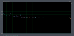
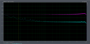
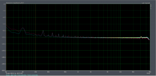
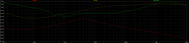
Using the cap multiplier lowers the 100Hz ripple under the noise floor. I had to short the cap multiplier to get the 100Hz ripple higher than the noise floor. I used the 60dB LNA in these measurements, so you'd add 60dB to the figures on the scale.
First measurement is LM317N. Pink trace is with cap multiplier shorted, green trace is with cap multiplier in circuit. Whatever is at 100Hz with green trace is 50Hz harmonic.
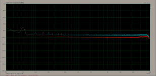
Second measurement is LM337N. Red trace is with tht Panasonic FR 100uF/50V on the output, green trace is with 2x10uF 1206 ceramic caps + 50mOhm resistor + around 30nH diy aircore inductor in series. Both traces are with cap multiplier in circuit.
Edit: from simulation the cap multiplier lowers the 100Hz ripple by around 47dB. So way lower than the noisefloor. Or at least what I measure as being the noisefloor. I can get a lower noisefloor by increasing the FFT resolution, but it takes much more time and I'm impatient for all measurements. There's also lots of 50Hz+harmonics parasitic, can't do much about those with my environment and gear.
2nd edit: The inductor choice can account for the 50mOhm series resistance that is needed. I found some that might do the job, but I think I'll include both R and L footprints on the pcb to make it easier. Even so, the resistance of the inductor has to be accounted for and you'd adjust the series resistor value for that. This needs more experimentation and I'd have to get the needed inductors + resistors on the next part order. Might be a while. I presume this extra inductance is needed for the to220 version of LM337. This would explain why it worked with some low esr tht electrolytic caps and not with other low esr I've tested with. I think this solves the mystery for the LM337 instabilities.
3rd edit: there's more to experiment with the comp network, I haven't found the lowest values LM337N+dienoiser works with. I used around 50nF+5R or something like that. I'll report back on this once I get some time to tinker. Needed capacitance might be lower. LM317N + dienoiser worked fine with 22nF and no R and with 33nF +3.9R.
Using the cap multiplier lowers the 100Hz ripple under the noise floor. I had to short the cap multiplier to get the 100Hz ripple higher than the noise floor. I used the 60dB LNA in these measurements, so you'd add 60dB to the figures on the scale.
First measurement is LM317N. Pink trace is with cap multiplier shorted, green trace is with cap multiplier in circuit. Whatever is at 100Hz with green trace is 50Hz harmonic.
Second measurement is LM337N. Red trace is with tht Panasonic FR 100uF/50V on the output, green trace is with 2x10uF 1206 ceramic caps + 50mOhm resistor + around 30nH diy aircore inductor in series. Both traces are with cap multiplier in circuit.
Edit: from simulation the cap multiplier lowers the 100Hz ripple by around 47dB. So way lower than the noisefloor. Or at least what I measure as being the noisefloor. I can get a lower noisefloor by increasing the FFT resolution, but it takes much more time and I'm impatient for all measurements. There's also lots of 50Hz+harmonics parasitic, can't do much about those with my environment and gear.
2nd edit: The inductor choice can account for the 50mOhm series resistance that is needed. I found some that might do the job, but I think I'll include both R and L footprints on the pcb to make it easier. Even so, the resistance of the inductor has to be accounted for and you'd adjust the series resistor value for that. This needs more experimentation and I'd have to get the needed inductors + resistors on the next part order. Might be a while. I presume this extra inductance is needed for the to220 version of LM337. This would explain why it worked with some low esr tht electrolytic caps and not with other low esr I've tested with. I think this solves the mystery for the LM337 instabilities.
3rd edit: there's more to experiment with the comp network, I haven't found the lowest values LM337N+dienoiser works with. I used around 50nF+5R or something like that. I'll report back on this once I get some time to tinker. Needed capacitance might be lower. LM317N + dienoiser worked fine with 22nF and no R and with 33nF +3.9R.
Attachments
Last edited:
Glad you've got it all figured out!
If you are up for some excitement, you could build three identical PCBs using your latest and greatest "fix", with (i) first board using ST Microelectronics LM337, as Elvee uses; (ii) second board using Texas Instruments LM337, as bad-luck VRDN builders have used; (iii) third board using ON Semiconductor LM337, as good-luck "humble self" has done.
Maybe they will all exhibit different oscillation behaviors! That would be a lot of fun to investigate.
I think only Texas Instruments makes LM317N/LM337N in sot223 flavor.
I also have the to220 variants for N versions. So these measurements should be valid for these only. I think the N versions are the "lower noise" variant for LM3x7.
I also have the to220 variants for N versions. So these measurements should be valid for these only. I think the N versions are the "lower noise" variant for LM3x7.
Also I think all those you mentioned used the denoiser not dienoiser. The dienoiser further pushes the performance.
Elvee had a working LM337 denoiser, and I think VRDN had a high 0.2R series resistor for the output capacitor. Was there anyone using any LM337 + denoiser and low esr output cap with no series R that had oscillations?
Elvee had a working LM337 denoiser, and I think VRDN had a high 0.2R series resistor for the output capacitor. Was there anyone using any LM337 + denoiser and low esr output cap with no series R that had oscillations?
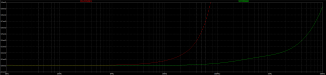
For the LM337 denoiser the dienoiser output cap configuration did not work, and I didn't try to figure out the correct values as using 2x Panasonic FP 100uF/25V smd caps (6.3mm diameter version) in parallel works just fine. They fit the footprints that already are on the dual smd board I posted. Compensation network for the LM337 dienoiser was 47nF + 3.9R and for LM337 denoiser I used 22nF+3.9R. This would conclude the LM337N sot223 measurements, I will adjust the board for the dienoiser output cap network configuration. But as can be seen from the comparison in the measurements the difference does not really justify the possible issues you might be having with implementing the dienoiser. I'll update the board design for people who want to go the extra mile and know what they are doing/have measurement gear. But since the ripple is lowered by cap multiplier also below de/dienoiser noisefloor you don't gain much by going to dienoiser, maybe the even lower output impedance at 10-20kHz. Attached the comparison between the denoiser/dienoiser for sot223 LM337N using 60dB LNA.
Attachments
I finally got to test the LT3082 on the smd board and with the recommended ceramic output cap it doesn't work. Adding the compensation network also messes the output voltage somehow.
But having the experience with the LM337 issues I decided to first try the denoiser + large electrolytic cap that worked with the LM337 denoiser and it works! I still need to try and use the RLC network for the output cap, pretty sure it works the same and the issue is with the needed inductance. Somehow the denoiser seems to be imposing this need.
What I find more interesting is the dienoiser type performance out of the denoiser. The attached measurement is the normal LT3082 output with 2.2uF cap on the adj pin, and then with the denoiser, using the same 2.2uF (moved it) to couple to denoiser circuit. Output seems rock solid at 12V, and I also poked at the denoiser nodes and it recovers instantly, no oscillation issues. Because the cap I used is so large I couldn't put the case cover on, that might help with the LF noise. Still to test further, but pretty interesting performance out of just the denoiser. I need to check the sim and confirm this. I'll also need to bypass the cap multiplier as I want to check the PSRR for the ripple. Also from simulation I expected the lower noise floor, which gets pretty close to what I can measure with the 60dB LNA.
Attachments
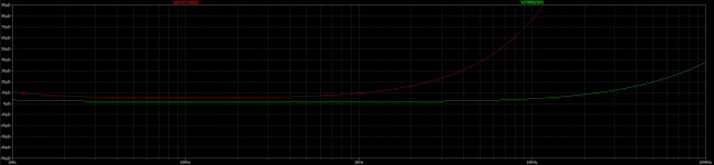
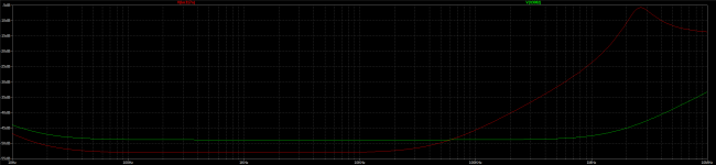
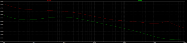
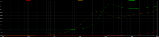
Also the simulation results comparing LM317N + dienoiser and LT3082 + denoiser. Both with the circuit on the smd pcb (CLC + cap multiplier). Pretty wild performance out of the LT3082+ simple denoiser.
Graphs for PSRR, self noise reduction and output impedance.
Graphs for PSRR, self noise reduction and output impedance.
Attachments
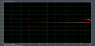
Also a comparison in measurements between LM317N + dienoiser and LT3082 + denoiser and no comp network. I still have to find the correct ranges for the output cap network but this looks promising. It should theoretically work with LT3080 as well. If I can make it work with a small ceramic output cap then this can be made very small, and should be incredibly attractive as an option for analog and digital as well. The HF performance in simulation looks very good and also the low output impedance from the simulation stays very low to 10MHz.
I'll also try the dienoiser with LT3082, if that works and also without comp network it would be crazy. Later I'll also have to test with some dynamic load.
edit: first graph green trace is LM317N + dienoiser and red trace is LT3082 + denoiser.
I'll also try the dienoiser with LT3082, if that works and also without comp network it would be crazy. Later I'll also have to test with some dynamic load.
edit: first graph green trace is LM317N + dienoiser and red trace is LT3082 + denoiser.
Attachments
Seems dienoiser works as well, also without compensation network (just as LTSpice simulation predicted!). Also solid, no issues. I tried the Panasonic FR 100uF/50V and it worked. Weirdly enough it didn't work so good with the denoiser, but no issues with the dienoiser.
Also added the ceramic output cap (3x10uF 1206) + 50mOhm (3x150mOhm) and around 30nH diy aircore inductor, and it works fine with the dienoiser. So apparently this extra inductance need is common to the denoiser/dienoiser. Should also be the case for LT1085. Will test tomorrow for LM317 + dienoiser and small ceramic output cap as well.
I also shorted the cap multiplier to get some 100Hz ripple above the noisefloor, and I noticed there's a difference between denoiser and dienoiser so that's reassuring the dienoiser actually works better for PSRR at least.
I made a comparison of LT3082+dienoiser measurements, with cap multiplier shorted and with it in circuit. I used higher FFT resolution. signals are "thinner" and there's more detail this way.
Graph attached, white trace is with cap multiplier shorted, red is with it in circuit, both measurements with dienoiser option and the ceramic cap arrangement on the output. You can notice the lack of any 100Hz ripple on the red trace with cap multiplier in circuit. This is right at the bottom of my measurement gear abilities. The LT3082 is about twice as expensive as LM317N in sot223 package.
edit: Noise floor seems under -160dB, and that means under around 13nV.
2nd edit: I used a 2.2uF 0805 coupling cap to dienoiser circuit, 12Vout with 1.2meg resistor for LT3082, 50mA current draw. Denoiser seems to take a few seconds to settle, but the dienoiser is an absolute beast, takes max two seconds. It basically jumps from lowest noise floor while off to running noisefloor level, no overshoot no nothing. Straight to work instantly and stays there.
Attachments

Last edited:
This would be rev1.3 for the smd boards, single and dual, diy and fab versions for each. For DIY you need to link the voltage setting resistors to ground with a small wire loop. There's pads for that. I added the output capacitor network footprints. You can either use the boards with the denoiser with smd electrolytic caps either the dienoiser version with LM337N and LT3082 using the RLC network footprints for the output cap. They are 2x1206 in parallel for the cap and 0805 for each resistor and inductor. Looking at the inductor offerings in the 30nH range it seems you could easily diy one.
LT3082 doesn't need protection diodes so you don't install those for it.
I increased the 220uF cap physical size, the one from cap multiplier. It's now 8mm diameter so it's easier to find one. The diy version of the dual is the one I made my tests with so I presume both designs could be considered as tested. The single is basically mirrored on the dual version, apart from the input bridge rectifier. LT3082 is ok with 2.2uF denoiser coupling cap, 220uF is needed for LM3x7. For low output voltages like 3.3V you'd use 3.3-4.7uF max.
Next I'll test the coax sensing setup. The tests I made were with the load next to the pcb in an aluminium case. At the moment I recommend you close the sense jumpers for the denoising circuit to sense the noise at the output of the pcb. Both boards have smd fuses on the input. The only thing that I'm unsure of are the cooling planes on the back. They are not ground and I don't know if they'll pick noise or not. They have no current running through them. They do help with cooling.
edit: single board is 62mm x 28mm and dual board is 67mm x 47mm.
Attachments

Last edited:
Since I made a previous test design with a LT3082+dienoiser small supply I decided to finish it since I got LT3082 + dienoiser working. It has an input LC filter. This should be very good for digital use, 3.3Vout. Seems it's happy with 5Vin. Looking at the simulation this should have better performance than datasheet application of LT3042 or ADM7150 at 3.3Vout. Possibly at 5Vout as well but I did not test it. I attached the sim file so you can play with it. PSRR is better than LT3042 or ADM7150, low and high frequency. For output impedance the LT3082 + dienoiser has extremely good performance 10Hz-10MHz, at least looking at the simulation. I remember reading something about output impedance mattering for digital clocks, so this would fit perfectly for digital use. BOM without 0805 resistors and output inductor (haven't tested any so I can't recommend one) is around 1$ more expensive than a single LT3042 chip, and cheaper than a single ADM7150 chip.
LT3082 is a 200mA device, and at max current output for 5Vin and 3.3Vout the device dissipates around 310mW which should be fine and shouldn't need any heatsink.
I also tested on my diy dual board if the LT3082 + dienoiser has any issues with 10nF and 100nF on the output, I bypassed the RLC output network, and seems to be working fine. I also tried with 100nF and 10nF in parallel and it also worked fine. These should be most cases on digital chips, most use any or a combination of these on their power inputs.
Of-course this supply is not tested, you make it at your own risk! But simulation and my practical results indicate that it should be a very good performer. If you install it next to the load you can benefit of the crazy low output impedance. The overall size is similar to a TO220 package. Attached the kicad project with gerbers, also BOM file (without 0805 resistors and output inductor) and LTSpice sim file. Looking for inductors I saw some that are basically just the wound wire in aircore format. So looking at my results I'd say you could just try to make the small inductor. I used the calculator here:
Single layer air coil calculator
I needed around 4 turns on a 2mm drill bit I think. Try to shoot for around 30nH, a bit more I don't think it hurts, try not to get it lower than that.
edit: BOM parts are indicative, you can choose better input/output capacitors if you wish. Mind the voltage ratings if you'll use it for higher output voltages.
Also LT3082 needs a 330K output voltage setting resistor for 3.3Vout, 500K for 5Vout etc.
Attachments
Last edited:
I tested some more to find the range of resistance on the output cap network. I noticed I was using 3x10uF or 4x10uF 1206 caps in my tests. Trying to figure out the lowest capacitance the LT3082 + dienoiser is happy with I noticed that removing caps made it unstable. So I started suspecting the resistance. I used 50mOhm in series with the caps and also the diy inductor. I made some calculations and seems the diy aircore inductor would have around 30mOhm. So basically removing caps increases the total ESR. I started lowering the series resistor value and started working again. With 2x10uF 1206 caps it worked with 30mOhm series resistor. I managed to get it stable using a single 1206 10uF capacitor using 18.5mOhm series resistance. It doesn't work without any resistor, so I presume the 15-20mOhm are needed. It worked fine with 30mOhm + 2x10uF 1206 and also with 2x22uF 0805. Poked at the dienoiser bits and recovered fast every time. I'll have to try to find the range for the inductance as well, didn't have more time to play with that.
As it happens there's electrolytic capacitors that meet the requirements. 40-50mOhm ESR ones should do. Intuitively I'd say to go for thin and longer ones, I presume they'd have a higher ESL? Longer electrolytic caps seemed to work in my tests. Shorter ones, even with lower ESR were on the edge or caused issues. LT3082 + dienoiser is certainly experimental at this point, but hope my findings help you if you decide to make one. I wouldn't recommend it to beginners at this point, until I figure out certain parts that can be easily obtained that keep it happy. So far sandwiching 2x 1206 or 0805 10uF caps + 30mOhm resistor + a small diy aircore inductor seems to work fine.
As it happens there's electrolytic capacitors that meet the requirements. 40-50mOhm ESR ones should do. Intuitively I'd say to go for thin and longer ones, I presume they'd have a higher ESL? Longer electrolytic caps seemed to work in my tests. Shorter ones, even with lower ESR were on the edge or caused issues. LT3082 + dienoiser is certainly experimental at this point, but hope my findings help you if you decide to make one. I wouldn't recommend it to beginners at this point, until I figure out certain parts that can be easily obtained that keep it happy. So far sandwiching 2x 1206 or 0805 10uF caps + 30mOhm resistor + a small diy aircore inductor seems to work fine.
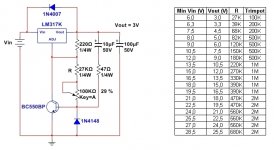
Which were the asc schematics you used for the circuits you actually measured on the last pages?
I would like to compare those curves to what LTSpice shows.
For me, that I do not use or really feel insecure with SMD parts it's a pity you didn't try through hole parts, though perhaps ESR and ESL might be too different. Is that so?
I would like to compare those curves to what LTSpice shows.
For me, that I do not use or really feel insecure with SMD parts it's a pity you didn't try through hole parts, though perhaps ESR and ESL might be too different. Is that so?
Last edited:
I attached the sim file. I got the sot223 versions for LM3x7N and wanted to test them. Also I got the LT3082 and the smd board was the best option for this. I will maybe try the tht board versions, but the results should be similar with cap multiplier.
I also got the LT3082 as I plan to use it on a DAC pcb. The tht version that should be similar I think is LT3080, but I have no use for it and it's also more expensive. For analog LM317N+dienoiser should be good enough for most needs.
I suppose the N versions for LM3x7 are actually better binning?
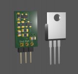
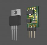
I tried a Panasonic FR 100uF/50V with the LM337N dienoiser and it worked. There's THT single electrolytic capacitors that have all required characteristics, ESR and ESL. The issue with the LM337 and LT3082 dienoisers was using small value ceramic capacitors on the output. For a small compact size that is desirable instead of the larger THT electrolytic caps. The needed inductance can be easily made with enamel wire. For the around 30nH I was able to make with 4 turns on a 2mm drill bit, 8 turns on a 1mm drill bit and also 5 turns on a 1.5mm drill bit (0.2mm diameter wire), and all worked fine. In the picture are the 5 and 8 turns versions, and the 5 turns version (1.5mm diameter) seems closest to a 0805 footprint as length.
For the LM337N smd there's really no smd electrolytic option that would work with the dienoiser. Most caps in that size have around 160mOhm ESR, and even paralleling two of them doesn't get low enough for the dienoiser. 2x Panasonic FP 100uF/25V seems to work for denoiser, but not for dienoiser. So the only option for smd format is using ceramic caps, which require the extra ESR/ESL. Same for smd LT3082.
I also got the LT3082 as I plan to use it on a DAC pcb. The tht version that should be similar I think is LT3080, but I have no use for it and it's also more expensive. For analog LM317N+dienoiser should be good enough for most needs.
I suppose the N versions for LM3x7 are actually better binning?
it's a pity you didn't try through hole parts, though perhaps ESR and ESL might be too different. Is that so?
I tried a Panasonic FR 100uF/50V with the LM337N dienoiser and it worked. There's THT single electrolytic capacitors that have all required characteristics, ESR and ESL. The issue with the LM337 and LT3082 dienoisers was using small value ceramic capacitors on the output. For a small compact size that is desirable instead of the larger THT electrolytic caps. The needed inductance can be easily made with enamel wire. For the around 30nH I was able to make with 4 turns on a 2mm drill bit, 8 turns on a 1mm drill bit and also 5 turns on a 1.5mm drill bit (0.2mm diameter wire), and all worked fine. In the picture are the 5 and 8 turns versions, and the 5 turns version (1.5mm diameter) seems closest to a 0805 footprint as length.
For the LM337N smd there's really no smd electrolytic option that would work with the dienoiser. Most caps in that size have around 160mOhm ESR, and even paralleling two of them doesn't get low enough for the dienoiser. 2x Panasonic FP 100uF/25V seems to work for denoiser, but not for dienoiser. So the only option for smd format is using ceramic caps, which require the extra ESR/ESL. Same for smd LT3082.
Attachments

Last edited:
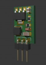
This is how the inductor would look on the 0805 footprint.
Attachments
Last edited:
I tested LM317N sot223 +dienoiser with ceramic output cap and seems to work. I used a 1206 10uF cap + 150mOhm + 30nH inductor. Seemed very stable.
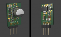
I made the same design for LM317N and LM337N in sot223 package. I removed the input inductor as it didn't fit, and the scope of these supplies would be more for analog stuff. For digital the LT3082 version would work better. The pcb size is identical between all three versions, around 11mm x 17mm. These designs have not been tested yet, you make them at your own risk! I might send these three designs to the fab house, seem very useful in the small size. I presume they should be good for 200mA, maybe a bit more but you need to keep a small voltage across them. You could use them up to 23Vout if you install the correct voltage rating caps.
BOM cost should be around 4-5$ without resistors for each. The 220uF coupling cap is 6.3mm diameter and you should be able to find it in 25V rating as well. Not many but you can find some. I think they all are 7.7mm tall. 16V rated ones can be found in 5.8mm height.
edit: These should be used only with dienoiser. The denoiser changes the output cap characteristics requirement vs dienoiser. From my tests the comp network for LM317 dienoiser should be 22nF + 0R or 33nF+3.9R, and for LM337 dienoiser around 47nF+3.9R. Output cap network for LM317 dienoiser 10uF + 150mOhm + 30nH, and for LM337 would be best to sandwich 2x10uF 1206 caps + 30mOhm + 30nH.
Attachments

Last edited:
- Home
- Amplifiers
- Power Supplies
- D-Noizator: a magic active noise canceller to retrofit & upgrade any 317-based VReg