I must be missing something here. When I calculate the ESR for MY 100µF capacitor (Nichicon UHV1V101MED1TA, 100µF, 35v, tanδ = 0.11@120Hz) and using the formula:
E.S.R. = DF / 2 Pi f C, I get 1.46 Ω. That's a far cry from the coupla-hundert milliohms that everyone here is talkin'. Huh?
Well, I didn‘t calculate this, but only referred to the datasheet value at 100 kHz.
How the cap behaves at 120 Hz, I have no idea. Which frequency range is relevant for the ESR in terms of stability anyway? 120 Hz is mostly relevant for the rectification of AC current.
Well, it's confusing to me. Resistance doesn't normally vary with frequency, but in the case of ESR, apparently it does. At 120Hz, the 100 uF cap is 1.46Ω of ESR and 13.3Ω capacitive impedance; yet at 100KHz, the datasheet says 0.10Ω impedance. But, I do agree, the 100KHz impedance is probably the relevant figure for stability.
Well, it's confusing to me. Resistance doesn't normally vary with frequency, but in the case of ESR, apparently it does. At 120Hz, the 100 uF cap is 1.46Ω of ESR and 13.3Ω capacitive impedance; yet at 100KHz, the datasheet says 0.10Ω impedance. But, I do agree, the 100KHz impedance is probably the relevant figure for stability.
It's confusing if you think of a capacitor as resistor, which is mostly linear and it works both with DC and AC.
Resistance on a capacitor is non-linear and only at AC. That's why it varies with frequency.
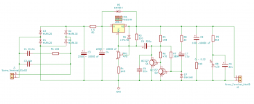
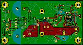
LM317 regulator design is supplemented with negative rail LM337 design. It uses same layout as LM317 with minor necessary changes. Compensation capacitor has resistor in series. As kumori determined, LM337 dienoiser is stable with combination of 20 nF + 27 Ω and output capacitor ESR around 300 mΩ.
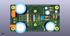
I decided against both rails on the single pcb, as separate pcbs provide flexibility and I don’t have to design 3rd pcb. 😀
I decided against both rails on the single pcb, as separate pcbs provide flexibility and I don’t have to design 3rd pcb. 😀
Attachments
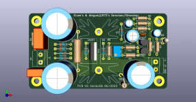


@tombo56 Thank you for your contributions to thread. Btw, separate pcb means two independent transformer windings (or transformers) without center tap. Two positive regulators is just enough if we are going two use two separate rails since we can use positive rail as negative one. Negative rail only makes sense in combination with positive rail with center tap transformers in practical aspect.
Last edited:
Two LM317 dienoiser V1 pcbs free of charge
At Tuesday I will be sending two LM317 denoiser V1 pcbs to one forum member. I have 2 more to go. If anyone needs one or both, just send me PM with shipping address. I will send them free of charge with ordinary untracked letter, so it costs me almost nothing, even for the address at the “end of world”.
Unfortunately, this is currently guaranteed to work only for the addresses inside EU and some destinations around the world, as ordinary postal traffic is cut off among many countries.
I don’t know but there is a good chance they will work. Someone will have to try and report back.
... Negative rail only makes sense in combination with positive rail with center tap transformers in practical aspect.
These PCBs can also be used with a single transformer having a single (non center-tapped) winding, by stuffing some diodes and omitting others, so as to build a pair of half wave rectifiers. This does however require you to use a positive regulator board (with LM317) for the positive supply, and a negative regulator board (with LM337) for the negative supply.
Of course, half wave rectifiers do have about 2X the ripple, since they recharge the filter capacitors half as often. On the other hand, they let you use an AC wall wart as your transformer -- which removes the transformer from the audio equipment entirely, reducing the total volume and size of the chassis. Since the AC mains voltages are no longer routed into the audio gear, it's less dangerous too.
As kumori determined, LM337 dienoiser is stable with combination of 20 nF + 27 Ω and output capacitor ESR around 300 mΩ.
Please be aware: I always referred the de-noiser (not die-noiser). Also, the compensation with lm337 could be less eventually, for example 10nf and 10Ohm. I did not test all iterations, but was happy that it worked at some point. Of course your pcb is prepared for every scenario, so this should be no problem.
It's quite interesting that actual boards are being prepared, carefully designed, both for the Denoiser and the Dienoiser.
It would be interesting if both measurements and listening tests for both were carried on.
I think a participant of this topic was trying these regulators in actual commercial products, and I would be curious to know how both regulators compare to other types, particularly the Superregulator and those using LT3042/45.
Those have been around for some time, and I think are considered to be among the best available. So a comparison might be very useful. Until now we just have simulations, which can be deceiving sometimes, like was recently shown with the oscillations that didn't show on simulations.
I think I'll wait to see what measured data @carlmart posts, before I decide whether or not to post my own measured data. Maybe his will be spectacularly thorough, precise, and comprehensive. If so there's no need for mine. Not to mention the embarrassment of a looser sigma.
I think I'll wait to see what measured data @carlmart posts, before I decide whether or not to post my own measured data. Maybe his will be spectacularly thorough, precise, and comprehensive. If so there's no need for mine. Not to mention the embarrassment of a looser sigma.
I can't publish or will publish any measured data, because I don't have the necessary instruments.
I can't publish or will publish any measured data, because I don't have the necessary instruments.
Would one need measurement amplification at these levels?
Something like this perhaps? Low Noise Measurement Preamplifier
Yes, and also some expensive instruments.
And most important: know how to use them and know what you are doing.
And most important: know how to use them and know what you are doing.
All you need is decent LNA(i made one for 20$) and good enough u-voltmeter. I have distortion analyzer HP 334A that can measure 300uV full scale so with 100x LNA that is 3uV resolution. If i recall i measured on my dnoiser PCB noise around 1uV.
The next step after measurements, including other respected regulators, like the Jung superregulator and other, come the listening tests.
Some reviewing sites do not carry on listening tests, and other magazines simple do not do measuring tests, and both are wrong.
It's important to correlate results obtained in both kind of tests.
Some reviewing sites do not carry on listening tests, and other magazines simple do not do measuring tests, and both are wrong.
It's important to correlate results obtained in both kind of tests.
Reversed LED polarity error
While adding LED pilot indicator my brain decided, without notifying me, that LED diode should be reversed polarity like Zenner diode. Today, some leftover brain cell kicked in and I spotted mistake.
If anyone ordered the pcbs it’s no big deal. Just mount LED in reverse to markings on the silkscreen. Corrected gerbers in attachment. Sorry for any inconvenience.
Attachments
Do you have a link or a schematic for such? Thanks.All you need is decent LNA(i made one for 20$) and good enough u-voltmeter.
- Home
- Amplifiers
- Power Supplies
- D-Noizator: a magic active noise canceller to retrofit & upgrade any 317-based VReg