would you please confirm that single tht LM 317 regulator with dienoiser and C L C pcb from post 1866 Is 80 mm long
That's 88.5mm long. The one from post #1872 is 80mm long but is without L and I consider that design deprecated as the last one without the inductor is even shorter and also has a shorter output trace.
LT1085 3.5A version is 74mm long as well.
Last edited:

For sure you need a heatsink, just that you mount it on the side of the pcb. You can mount them to a case, you can also drop them on the bottom of the case if it's good for moving heat away from them.
I made rev 1.2 without the inductor, and optimized the output trace. It's now shorter, I moved the output connector. The board is now also shorter at 74mm x 37mm.
Could you please make a dual version too? I mainly use +/-15v and +/-24v. 1.5A is perfect for my need.
Could you please make a dual version too? I mainly use +/-15v and +/-24v. 1.5A is perfect for my need.
Check post #1865
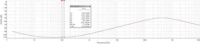
Is the climbing noise level around 50-100kHz normal? I'm not 100% sure this is stable. I installed two of the SMD small boards in a Hafler DH110 preamplifier.
View attachment 904267
That may be due to the limited ADC capture range? Audio cards are 20Hz-20kHz rated. Past that they may still do something but I wouldn't trust it.
To check whether it is oscillating or not, the most reliable method is to probe the collector of the transistor with an oscilloscope.Is the climbing noise level around 50-100kHz normal? I'm not 100% sure this is stable. I installed two of the SMD small boards in a Hafler DH110 preamplifier.
View attachment 904267
You can also try to short the C-E of the transistor: this will defeat the denoiser and kill any oscillation, if present
Here is an example of oscillation behavior on a DeNoiser circuit. The probe was on the IC voltage regulator's "ADJ" pin, which is just about the same as the BJT collector, since they are coupled together by a 220uF capacitor.
If you're wondering what settings to use on your oscilloscope, this example may help. Vertical amplifier + probe set to AC coupling, horizontal sweep 1 microsecond per grid, vertical scale 0.5 volts per grid, trigger level 0V [ac coupling!!]
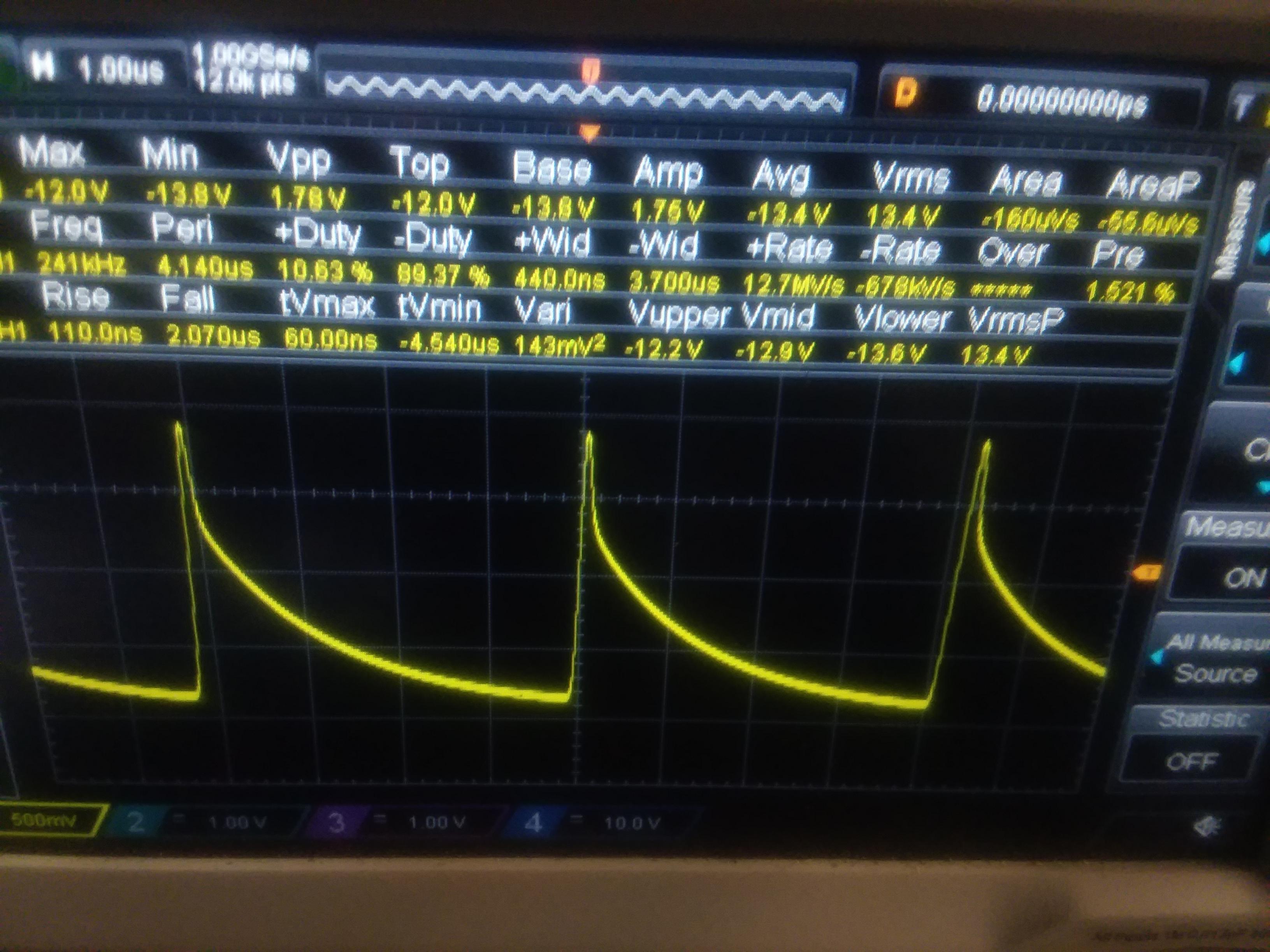
If you're wondering what settings to use on your oscilloscope, this example may help. Vertical amplifier + probe set to AC coupling, horizontal sweep 1 microsecond per grid, vertical scale 0.5 volts per grid, trigger level 0V [ac coupling!!]
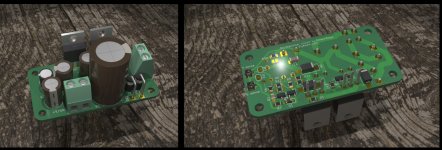
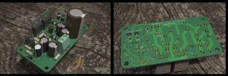
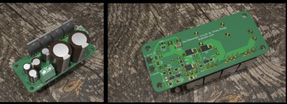
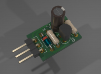
I started to play with Blender rendering and when I added the correct model for the 2200uF/35V cap I noticed it's very tall. Looks a bit silly, so I decided to remake the tht boards using 16mm cap size. Now there's only one on the input, boards got smaller, I also replaced the tht resistors/diodes footprint with shorter ones. There's a 2200uF/35V Panasonic FR 16mm cap as alternative. With only one for the LM317 it gets close to the max ripple current rating of the cap. Still under but it's close. I guess for music it should be ok. LT1085 board has two 16mm caps on the input, and at 35V rating with 24VAC input you get max 23VDC out, higher ripple, lower minimum voltage on the first cap. If you can get away with 25V rating on the first cap there's 3300uF Panasonic FR caps in 16mm size.
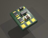
The fab house version of LM317 tht board and the LT1085 board have smd for what was possible. This way the boards got smaller while still delivering the max current for each IC.
Fab house version of LM317 board is 57mm x 30mm.
LT1085 board (only fab house) is 68mm x 30mm.
DIY version for LM317 board is 70mm x 37mm.
DIY version for dual board is 78mm x 62mm.
The renders should be pretty close to actual component sizes.
These are v1.3, and the only BOM component that changed is the 2200uF/35 12.5mm Panasonic FR cap, to the 16mm version. Previous BOM is not accurate for each board as some parts became smd on this revision but I used the same parts from the smd boards, so you can find each part in the BOM.
These boards have not been tested and you make them at your own risk!
Attachments
-
single_diy.zip169.8 KB · Views: 68
-
dual_diy.zip280.5 KB · Views: 68
-
lt1085.zip150.4 KB · Views: 65
-
single_small_fab.zip149.8 KB · Views: 60
-
 Screenshot from 2020-12-28 00-39-58.jpg310.3 KB · Views: 366
 -
 Screenshot from 2020-12-28 00-39-30.jpg322.5 KB · Views: 387
 -
 Screenshot from 2020-12-28 00-39-01.jpg327.9 KB · Views: 362
 -
 Screenshot from 2020-12-28 00-38-29.jpg435.9 KB · Views: 368
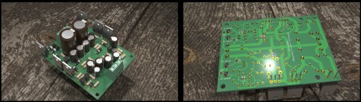
I bring one of my crazy spawn. I am hopeful that it can work acceptably well.
In PSRR it behaves comparable to the Elvee Denoiser. It lacks overshoots in the connection transient (only a delay in showing all the output voltage, but nothing to worry about). The most unfavorable point would be a slight shift in voltage with temperature, although not very marked in a wide thermal variation.
Drains less current than Denoiser.
Best regards
Attachments
Last edited:
Also I notice that this new version keeps a higher performance down to 3.3V output. The performance doesn't seem to suffer that much while lowering the output voltage, and that seems to be valid for PSRR, self noise and output impedance.
Interesting. Are you going to make this new revision? I’m about to send out the gerber for some dual boards made.
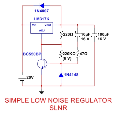
It is no longer a retrofit or upgrade and does not lend to simple setting of intended output voltage.... Since there's no 220uF cap ...
Yes you'd need to remove the original output voltage setting resistor and replace it with this board. I think it's the same with the nonoiser as far as application goes.
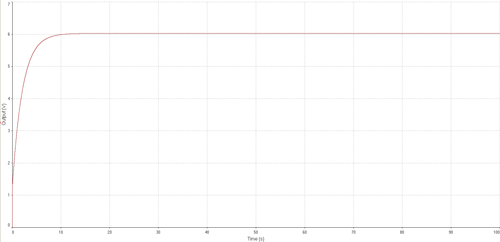
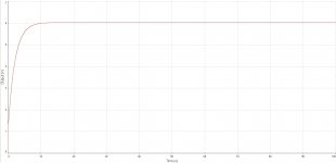
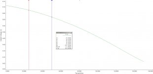
I tried to upset it with some pulses to see how it recovers but doesn't seem to be doing that good. Maybe I got something wrong in the sim? Let it run for some seconds.
I tried to upset it with some pulses to see how it recovers but doesn't seem to be doing that good. Maybe I got something wrong in the sim? Let it run for some seconds.
Attachments
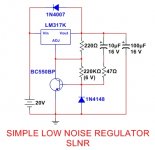
To set higher output voltage values so that the collector-emitter resistor of the BC550 does not acquire such high values, one possibility involves reducing the 220 ohm resistor to something like 100 ohms, thus with a collector-emitter resistor near 390 K, it should approach 15 V for hFE values around 300.
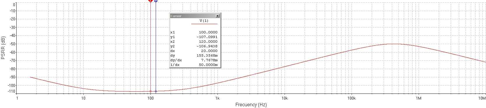
For resistor values like this, the output voltage varies down around 55 mV, between 25 ° C and 50 ° C, for example. ( aprox. - 2,2 mV / °C )
Best regards

For resistor values like this, the output voltage varies down around 55 mV, between 25 ° C and 50 ° C, for example. ( aprox. - 2,2 mV / °C )
Best regards
Attachments
Last edited:
- Home
- Amplifiers
- Power Supplies
- D-Noizator: a magic active noise canceller to retrofit & upgrade any 317-based V.Reg.