This new version is more a cap-multiplier on steroid than a regular voltage regulator.
The output voltage will change heavily, depending on the exact transistor used (not only the type # or even the selection), and it will further change with temperature.
If an accurate voltage is required, a trimmer is unavoidable
The output voltage will change heavily, depending on the exact transistor used (not only the type # or even the selection), and it will further change with temperature.
If an accurate voltage is required, a trimmer is unavoidable
The weak point is the variation of Vout with temperature, which is not far from - 2 mV / ° C for the vast majority of transistors that I have simulated.
It is attractive for its almost extreme simplicity and the fact that it does not present overshoots in its output, something that both denoisers and dienoisers suffer.
Another point that adds up is that it is possibly stable for both types of regulators, although it would have to be tested.
There are no perfect solutions throughout the entire range of parameters.
All variants suffer from something.
Best regards
Last edited:
I advise you to build 2 - 3 units for a target output voltage and also note the temperature stability to understand. The models used in your simulation are not complete so they can not show you the inherent problem.
Stay calm. I understand very well the problem that this circuit has. They will be factors that will have to be observed, chosen and adjusted.
Best regards
Attachments
Last edited:
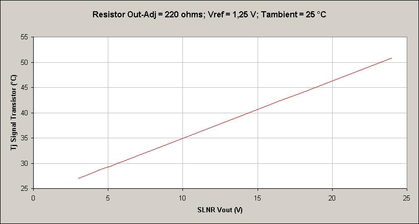
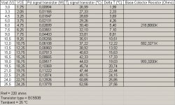
For a 15V application, the signal transistor will dissipate around 78mW, with Vref ratings for the LM317 of 1.25V and with a 220 ohm resistor between the output and adj pins.
Thus, the Signal Transistor Tj would reach about 40.6 ° C, with a Tambient of 25 ° C. That is, 15.6 ° C above the Tambient.
Best regards
Thus, the Signal Transistor Tj would reach about 40.6 ° C, with a Tambient of 25 ° C. That is, 15.6 ° C above the Tambient.
Best regards
Attachments
So, ~ 1 V / °C ?
Night and day ambient temperature difference around my house is about 7 - 8 °C, how much will that affect the "regulated" output voltage?
Night and day ambient temperature difference around my house is about 7 - 8 °C, how much will that affect the "regulated" output voltage?
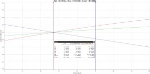
No. That last graph defines what temperature the junction reaches according to the programmed output voltage, considering that the collector current of the signal transistor is approx. about 5.68 mA (1.25 V / 220 ohms), neglecting the Iadj.
That is, for an application where Vout is 15 V, the power dissipated in the transistor would be about 78 mW. (13.75 V x 5.68 mA). With that power dissipated and an Rthj-a of 200 ° C / W (typical of a BC550), the Tj would reach 0.078 W x 200 ° C / W + 25 ° C = 40.6 ° C.
So they are only 15.6 ° C above the Tambient of 25 ° C. Assuming that a coefficient of - 2 mV / ° C can be adjusted and strategically chosen (according to transistor), they would imply 31.2 mV of variation from when the power supply is connected until its temperature stabilizes.
And so I define the graph for each output application voltage.
Best regards
Last edited:
Amazing. I am at loss of words Horacio. Just wait for others to complain, hopefully before fatal mishaps.
Last edited:
The standard trick to reduce sensitivity to deltaVBE, is a (heavily!) bypassed emitter resistor.
Maybe our friend Trileru with his great measurement setup, build it and check how well or badly it works 😀😀😀.
A trimpot instead of the resistor between collector and base, would allow to more precisely adjust the output voltage, or also play with the 220 ohm resistor, or play with both.
Best regards
A trimpot instead of the resistor between collector and base, would allow to more precisely adjust the output voltage, or also play with the 220 ohm resistor, or play with both.
Best regards
Happy new year!
At the moment I'm working at testing the smd dual board. So far sot223 LM317N dienoiser works great. I managed to get the sot223 LM337N dienoiser stable as well, just need to pin down the correct output cap esr and comp network that would have good margins for anyone wanting to make the board. After I'm done with this I might give the SLNR a try.
At the moment I'm working at testing the smd dual board. So far sot223 LM317N dienoiser works great. I managed to get the sot223 LM337N dienoiser stable as well, just need to pin down the correct output cap esr and comp network that would have good margins for anyone wanting to make the board. After I'm done with this I might give the SLNR a try.
Happy new year to all!!!.
I will look forward to that test.
I am convinced that the SLNR will not disappoint (great simplicity and economy of construction). I think it should be stable without compensation networks of any kind.
Best regards
I will look forward to that test.
I am convinced that the SLNR will not disappoint (great simplicity and economy of construction). I think it should be stable without compensation networks of any kind.
Best regards
I'm having some issues that I don't really understand. I'm testing the sot223 LM337N + dienoiser circuit and seems there's some other differences between capacitors that I can't figure out.
For example, the circuit is stable with very good performance using a Samxon 2200uF/50V electrolytic cap, it's pretty large, and has a ESR of under 50mOhm. It's also working fine with a 100uF/50V Panasonic FR which has ESR of 61mOhm. But using ceramic capacitors with series resistance doesn't work. I tried all values of capacitance between 100-200uF with 150mOhm, 75mOhm, 50mOhm and 37.5mOhm series resistance. I used the same footprint for all tests.
I also tried two smd Panasonic FP 100uF/25V caps in parallel, each has 160mOhm ESR so that would come out a bit higher at 80mOhm, and it also didn't work.
What else could differentiate the different configurations? Inductance?
The circuit seems to work fine with the 100uF/50V Panasonic FR, which is good as it's a physically small capacitor. But I would have liked to find a smd configuration.
What is the amplitude and frequency of the oscillation?
Can you make the oscillation appear and disappear by changing the output (load) current?
Can you make the oscillation appear and disappear by dialling the potentiometer which sets the output voltage? Try 9V, 13V, 17V, 21V
Can you make the oscillation appear and disappear by touching various component bodies and various component leads, with a moistened fingertip?
I don't have an oscilloscope to properly check that. I'm using my LNA and I'm looking at the FR of the output noise. There's usually two different not working scenarios, either the ADC goes into protection from exceeding the max input, either the noise "wobbles" in the ADC's capture range. There's also the scenario where it's stable but noise is not lowest as should be, but that is a rarer scenario in my testing.
When it's stable and I touch different sensitive parts it goes wild for a fraction of a second but instantly recovers. If I do that while it's not properly working nothing happens as usually the ADC is flooded with noise, and goes into protection.
I'm only testing at 12Vout as it would bee too much pain to go the other way around. I first want to make it stable at this output, then go to different output ranges and see if it's stable there as well.
Load current is 50mA, I'll vary that once I get a stable configuration at 12Vout/50mA.
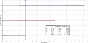
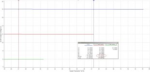
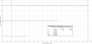
These curves look like simulation quirks: both the Vbe and Hfe temperature dependence should result in a negative tempco; seeing the opposite behaviour probably means that the sim misses something important.Stay calm. I understand very well the problem that this circuit has. They will be factors that will have to be observed, chosen and adjusted.
Best regards
I tried again today to sort the LM337N + dienoiser smd circuit but can't figure out what the issue is. It works with a Panasonic FR 100uF/50V on the output. It has an ESR of 61mOhms. I tried to emulate it with ceramic caps. I sandwiched a few to 100-120uF with 50mOhms series resistance and it isn't stable. More strange, if I parallel that arrangement with the FR cap, it works nice again but the ESR is even lower this way. So there's something special about that tht electrolytic cap. And about other tht electrolytic caps. Seems there's like a larger physical size + correct ESR range, and above 50-100uF that works. But ceramic caps + resistor isn't working. Also physically small smd electrolytic caps don't work either. I tried paralleling a 470uF+100uF smd electrolytic with a combined ESR of 53mOhms and it also didn't work. But somehow when I add a physically larger tht electrolytic it works fine.
- Home
- Amplifiers
- Power Supplies
- D-Noizator: a magic active noise canceller to retrofit & upgrade any 317-based VReg