The question is if there is (similarly) good performance available for higher voltage (say 36v or 48v) ? Anyone any suggestions ?
For a 32V PSU I will use TL431 as in post #1040 and post #1092 positive regulator only.
This solution cannot do 48V, the limit is 36V because of the max voltage rating of TL431.
Indeed, fast transient loads are dreadful, especially at unloading, this is where I see stability troubles.It helps prevent oscillation and ringging if regulator is "smacked" with high and fast transient load.
It works together with RC compensation in the same direction achieving slightly better result.
Can you look at stability of the positive regulator in post #1092 with the upper resistor moved from cathode to output.
Almost, but not quite: 40V input and I don’t think it would play nice with several 10.000 uF low ESR capacitors at the output, as is usually found in the regular CRC power supply of a class A amplifier.
I find this as interesting development challenge and entertainment (popcorn not included), that eventually could be used in my amplifier builds.
Finally, how would LT regulator answer the concerns expressed in the neighboring thread?
Are you really fine with IC voltage regulators ?
As one can easily see new devices are mostly low power with local regulators close to the circuit (smart phones drive this probably as RF is a buzzword with such regs). 200 mA and 500 mA won't cut the cake for class A amplifiers but neither will their dinosaur brothers in stand alone config. Only IC regulator that came close was LT1083CP buit it was discontinued... For higher voltages and higher current I would be forced to design/build large and expensive discrete regulators but unregulated PSU's with CLC filtering generally are fine for such devices. It becomes way easier when one chooses a "small" amplifier, then suddenly a lot more is possible with respect to modern LDO regs.
The other thread has some stubborn guys (that is OK
 ) wanting to doubt performance of modern IC
  LDO regulators with a strong bias for discrete solutions. That is fine as no real high current LDO's are developed but it will be very hard to come even close to LT3042/LT3045.
It is also possible to develop the other way around: to find/design devices that perform excellent and can be used with 5V to 15V 3A max. PSU's
To my surprise I am perfectly satisfied with a 2 x 4W amplifier.
Last edited:
Hi, I had posted negative regulator circuits but got no attention, it might be explaining the theory of operation was not enough. Thus I post basic DC topological circuit first.
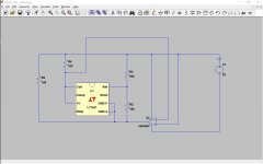
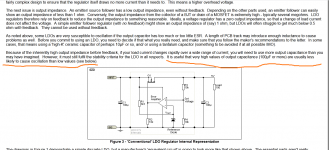
The first picture is it. LT1431 has extra pins compared to TL431 but the operation is not so different, I used it just as TL431. So, the anode is tied to the output, cathode goes to the noninverting input of error amplifier / pass transistor. The ref pin goes to a voltage divider, remember, the voltage between ref pin to anode pin is about2.5V, so the voltage between R2 is 2.5V then R3 will be 12.5V, totally 15.0V which is the output voltage.
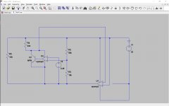
How is this possible? Well, in the TL431's datasheet you might see an equivalent circuit diagram comprised of a opamp and a NPN transistor. In the second picture, TL431 is replaced to that model. You can now clearly see this circuit has 2 stage feedback loop, negative and positive feedback. Negative feedback has no divider thus feedback ratio is 1, positive feedback has a divider to set the output voltage. This topology is very similar to LM317 and LM337, output voltage is set by equation Vref*(1+R3/R2).
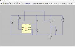
The third figure is an example of an error amplifier / pass transistor. You need to add compensation for stability because this circuit has at 2 HF roll off in TL431 and 2 or more in the discrete stage.
The first picture is it. LT1431 has extra pins compared to TL431 but the operation is not so different, I used it just as TL431. So, the anode is tied to the output, cathode goes to the noninverting input of error amplifier / pass transistor. The ref pin goes to a voltage divider, remember, the voltage between ref pin to anode pin is about2.5V, so the voltage between R2 is 2.5V then R3 will be 12.5V, totally 15.0V which is the output voltage.
How is this possible? Well, in the TL431's datasheet you might see an equivalent circuit diagram comprised of a opamp and a NPN transistor. In the second picture, TL431 is replaced to that model. You can now clearly see this circuit has 2 stage feedback loop, negative and positive feedback. Negative feedback has no divider thus feedback ratio is 1, positive feedback has a divider to set the output voltage. This topology is very similar to LM317 and LM337, output voltage is set by equation Vref*(1+R3/R2).
The third figure is an example of an error amplifier / pass transistor. You need to add compensation for stability because this circuit has at 2 HF roll off in TL431 and 2 or more in the discrete stage.
Attachments
Last edited:
Indeed, fast transient loads are dreadful, especially at unloading, this is where I see stability troubles.
Can you look at stability of the positive regulator in post #1092 with the upper resistor moved from cathode to output.
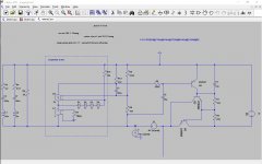
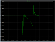
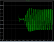
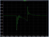
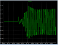
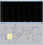
Regulator stability is generally the same for voltage divider connected to the input or output. Here is transient response while loading regulator with 1 kHz square wave 2A load with 1uS Trise & Tfall + 1 A constant load, shown at loading point. Unloading point is the same, with larger voltage swing.
First two pictures are for voltage divider (R2 & R3) connected to the output (Q3 collector) and with different R19 values, displaying damping effect. Second two are for voltage divider connected to the input or TL431 cathode.
Attachments
Thanks for the lt3042 article!As one can easily see new devices are mostly low power with local regulators close to the circuit (smart phones drive this probably as RF is a buzzword with such regs). 200 mA and 500 mA won't cut the cake for class A amplifiers but neither will their dinosaur brothers in stand alone config. Only IC regulator that came close was LT1083CP buit it was discontinued... For higher voltages and higher current I would be forced to design/build large and expensive discrete regulators but unregulated PSU's with CLC filtering generally are fine for such devices.
TL783 is a very similar device to lm317 except it works up to 125v Vin-Vout.I used it at even higher voltages(250v) by adj pin lifting with zener diodes as here:
Gyraf Audio - G9 DIY
It can be used the same as lm317 in all its known configurations.
TL783 is noisy. Way noisier than LT304x regs anyhow. I wouldn't use it for low voltage application. For higher voltage use there is not much choice in IC regulators so then it is a candidate.
This circuit seems to have 280 µV noise:
http://www.next-tube.com/articles/hvs/hvrEn.pdf
This circuit seems to have 280 µV noise:
http://www.next-tube.com/articles/hvs/hvrEn.pdf
Last edited:
A single cascode transistor could solve all the voltage issues without introducing any discernable degradation.
For example, with a 2N5551, 150V is reachable at a ridiculous cost.
A clever cascode arrangement could also solve the negative side problem without resorting to current mirrors: one just has to reference the cascode base to a fraction of the output voltage (with adequate temperature compensations, obviously)
As to high values of output capacitors there's a BUT outlined by ESP and although it looks like a very different issue it's basically the same issue as with loading some MC carts.Their manual advise for maybe 1nF loading, 2nf will sound like s...t and when you load them with a 22nf capacitor they suddenly sound better than the manufacturer's recommended value.
You can't maybe use an LDO with a 10uf low esr cap but you can safely use it with a 10 000uf low frequency ripple, high esr capacitor most of the time...
For more information: LDO Regulators
You can't maybe use an LDO with a 10uf low esr cap but you can safely use it with a 10 000uf low frequency ripple, high esr capacitor most of the time...
For more information: LDO Regulators
Attachments
Last edited:
Hi, I had posted negative regulator circuits but got no attention, it might be explaining the theory of operation was not enough.
This is DIY audio and hobby form, not an EE forum. You should post schematics that are easy to understand. For instance, your TL431 model has 4 connection points.
TL783 is noisy. Way noisier than LT304x regs anyhow. I wouldn't use it for low voltage application. For higher voltage use there is not much choice in IC regulators so then it is a candidate.
This circuit seems to have 280 µV noise:
http://www.next-tube.com/articles/hvs/hvrEn.pdf
The TL783 also needs much more input voltage than even an LM317, which might demand a multiplier if you do not want to pay for a higher voltage transformer.
It seems the thread is drifting off topic and I am guilty as well. I suggest keeping it to the denoizator by Elvee. Maybe the "IC regulator" thread is a better thread to discuss low voltage LDO stuff (let alone high voltage regulators).
Sorry but that is a wrong approach. If it would only be hobby stuff then we would still use LM317 Eh wait.... As you can see many DIYers use old parts and refrain from using newer techniques and recent SMD stuff to do just what they know. This is not a good reason not to use such excellent modern parts or new approaches with knowledgable people posting such theory.
Plus that you have not noticed it is a LT1431
This is DIY audio and hobby forum, not an EE forum. You should post schematics that are easy to understand. For instance, your TL431 model has 4 connection points.
Sorry but that is a wrong approach. If it would only be hobby stuff then we would still use LM317
Eh wait.... As you can see many DIYers use old parts and refrain from using newer techniques and recent SMD stuff to do just what they know. This is not a good reason not to use such excellent modern parts or new approaches with knowledgable people posting such theory. Plus that you have not noticed it is a LT1431
Last edited:
Sorry but that is a wrong approach. If it would only be hobby stuff then we would still use LM317
Plus that you have not noticed it is a LT1431
Guilty as charged
Well...TL783 can benefit of this denoiser too and may discard LT3042 as a better choice for higher supply voltages..
I'm thinking of using it for a vitual ground supply of +-25...30v using just one TL783 to regulate the total voltage. A discrete version is clearly more advisable for high voltage regulators than the Technics denoiser i'm using for lower than +-20v supplies but tl783 looks like a very neat solution.Maybe it would be a shame for Elvee's denoiser to be used as a preregulator for technics +-10 and +-20v denoiser versions i just finished , but at the same time i think of future lower noise high voltage diy consoles where this denoiser may be useful, especially with cascoded high voltage circuits that exhibit very poor PSRR. Not sure about that though...just thinking out loud.
I'm thinking of using it for a vitual ground supply of +-25...30v using just one TL783 to regulate the total voltage. A discrete version is clearly more advisable for high voltage regulators than the Technics denoiser i'm using for lower than +-20v supplies but tl783 looks like a very neat solution.Maybe it would be a shame for Elvee's denoiser to be used as a preregulator for technics +-10 and +-20v denoiser versions i just finished , but at the same time i think of future lower noise high voltage diy consoles where this denoiser may be useful, especially with cascoded high voltage circuits that exhibit very poor PSRR. Not sure about that though...just thinking out loud.
If you measure about 1.25V between ADJ and Output, this means LM317 works fine.
If you measures 0V at the ADJ, this means the 5K trimpot is set wrong or there a short.
Set the 5K trimpot half way and see what you get
Thanks for the insight. Wasn't getting voltage at ADJ no matter what the trimpot was set to.
Maybe you should debug by first setting up a regular LM317 PS without denoiser. Just connect C3 negative terminal to ground.
Great idea. LM317 does indeed seem to work, getting 17V out.
Last edited by a moderator:
Oh LDO, Where Art Thou?
How abut 150 dB PSRR at 0,65 V dropout from the simple regulator?
Thank you Shinja very much for pointing out at LT1431, and especially for the negative voltage variant. This opens new interesting possibilities. With denoiser circuit, which positively affects stability, it is about the same stable as version with the TL431. We will se about negative version.
Attachments
This is counter intuitive, at least for my intuition, but I saw it is likely true.Regulator stability is generally the same for voltage divider connected to the input or output.
I had presumed less stable when the divider is connected at the output versus at the input.
Then, I was amazed to see near no difference in the open loop gain, I saw the same phase margin.
Doing about the same, I had something strange. With some output capacitor ESR ( presumably bad values ) a spike occurs when unloading but not when loading.Here is transient response while loading regulator with 1 kHz square wave 2A load with 1uS Trise & Tfall + 1 A constant load, shown at loading point. Unloading point is the same, with larger voltage.
This using Trise & Tfall 1uS. Then I discovered the spike doesn't occur when using Trise & Tfall 0.1uS.
With steeper edges, the system looks more stable.
I cannot explain this weird behavior, it doesn't make sense, I am loosing faith in evaluating stability with .tran simulation.
I better count on open loop plot and phase margin.
I had a look to the LT1431 datasheet. It has all the same characteristics as the TL431.How abut 150 dB PSRR at 0,65 V dropout from the simple regulator?
Thank you Shinja very much for pointing out at LT1431, and especially for the negative voltage variant. This opens new interesting possibilities. With denoiser circuit, which positively affects stability, it is about the same stable as version with the TL431. We will se about negative version.
It is the same with more pins, it can do the same ( it even has a 3 pin version pin compatible to TL431) and it can do more. More pricey, too.
- Home
- Amplifiers
- Power Supplies
- D-Noizator: a magic active noise canceller to retrofit & upgrade any 317-based V.Reg.