... besides .... I would rather use 2 x LT317 instead of LT317 + LT337.
The LT337 has somewhat inferior noise figures.
Gimmick would require some serious rewiring though.
Since you get more than an order of magnitude lower noise with implementation of Elvee's gadget, the difference between LM317 or LT317 LM337 LT etc is not important.
For D7 and D8 use a 1N4149 in series with 22 ohms , (yes a 1N4149 has 1/2 the capacitance of a 1N4148). The 22 ohms prevents the diode being overloaded during reverse current flow.
Much lower capacitance than 1N4001 series diodes and less HF noise getting past the 317/337
Much lower capacitance than 1N4001 series diodes and less HF noise getting past the 317/337
Last edited:
(yes a 1N4149 has 1/2 the capacitance of a 1N4148).
And the Nexperia BAS21,215 has 1/3 the capacitance of a 1N4149. Thus 1/6 the capacitance of a 1N4148.
_
Attachments
Ok maybe you got me, but the Nexperia are surface mount.
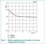
The data sheet for 1N4149 shows total capacitance as 2 pf and the Nexperia datasheet shows diode capacitance as 2 pf also, wheres the 1/3 capacitance chart and what does the 1N4149 Measure under that test? The In4001 type are 10 to 15pf depending on voltage and manufacturer. The UF 4007 are 17pf
The data sheet for 1N4149 shows total capacitance as 2 pf and the Nexperia datasheet shows diode capacitance as 2 pf also, wheres the 1/3 capacitance chart and what does the 1N4149 Measure under that test? The In4001 type are 10 to 15pf depending on voltage and manufacturer. The UF 4007 are 17pf
Last edited:
The role of D7 & D8 is to protect the fragile parts inside the 317 from being damaged by a load-dump event.For D7 and D8 use a 1N4149 in series with 22 ohms , (yes a 1N4149 has 1/2 the capacitance of a 1N4148). The 22 ohms prevents the diode being overloaded during reverse current flow.
Much lower capacitance than 1N4001 series diodes and less HF noise getting past the 317/337
Adding 22 ohm series will defeat the protection (load-dumps are generally caused by a discharge of a reactive component and can be violent).
A naked 1N414x will easily be melted by such an event, so if you estimate you need such a diode, use the proper part and bite the bullet of a (very moderate) degradation of HF PSRR, otherwise omit it completely.
This is not specifically related to the denoiser, it's a pure 317 thing, but the denoiser will help remove possible noise injected that way
I do not have the faintest idea.
As a first step, you could test it in TINA, if it's available in the libraries.
If it passes the first test, you can proceed to a breadboard prototype (or as a quick and dirty "flying" add-on to an existing regulator board.
Don't commit to a PCB before being 100% confident that it will work: so many things are different, so many things can go wrong
The subject of the thread is not the regulator in itself, but a circuit improving its performances.Is it possible to modify this regulator to output around +/- 70v to use on power amplifiers low current stages?
The denoiser could be applied to any 317-like regulator, except a 317 cannot work at 70V.
A TL783 could work, but its compatibilty must undergo a reality-check, as this has never been tested (it will probably work).
One would need to adapt some resistor values, the type of transistor and the voltage rating of capacitors, but I don't think it's worth the trouble: if your amp actually needs such a level of performance, you should scrap it and start afresh. Simply use a naked TL783.
It certainly works in your sense, but it would work even better if you tape your diodes + resistors somewhere inside (or even outside) the case.Actually the low capacitance diode with series resistor works despite your comments. I think the diodes don’t listen to you.
Leaving them in your components drawers would be the absolute best.
Under normal conditions, these diodes do strictly nothing.
Quoting the datasheet:
If you really want to test the effectiveness of your 1N4149 + 22 ohm, you can try to short the input, or discharge a 1000µF cap charged at 15V into the output, with the regulator unenergized.Diode D1 prevents CO from discharging thru the IC during an input
short circuit. Diode D2 protects against capacitor CAdj
discharging through the IC during an output short circuit.
The combination of diodes D1 and D2 prevents CAdj from
discharging through the IC during an input short circuit.
When these tests are done, please come back and inform us about the result...
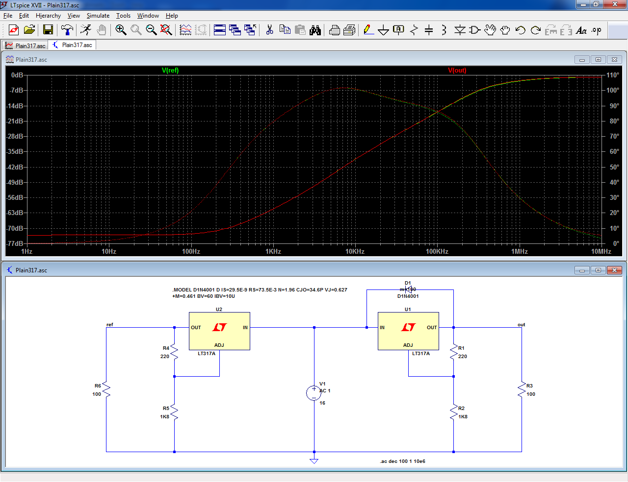
Regarding the effect of the diode capacitance, here is a sim comparing two situations zero capacitance, and 1N4001.
To make possible effects more visible, there are no capacitors at all, and the load is relatively light:
Look closely: there are two traces on the screen. Can you distinguish them?
Attachments
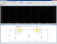
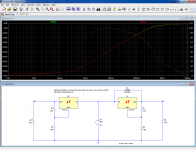
Even if you don't believe in sims, measurements and similar artificial evaluation means, here is the simulated effect of having 100 paralleled 1N4001's across the 317 (the parameter m=100):
You just begin to see two distinct curves.
Note that this is an "ideal" situation (sort of): the load is light, purely resistive, and there are no caps anywhere in sight.
If you add the normal caps for a 317, you would probably need 1,000 // diodes to see a difference between the curves, and with a denoiser this would rise to 10,000 or thereabout.
But if you can hear the difference, and if your 317 is better protected with your D+R network, I am certainly not going to contradict you: everyone has a right to his/her freedom space
Attachments
Is it possible to adapt the DeNoiser on a low current, high voltage 317/337 regulator, to be used to power the low current stages in some power amps I will be assembling?
The regulated output would be +/-67v, so the input would be around +/-75v, as those regulators are not LDO types.
But current will be less than 25mA, so heat sinking might not be necessary.
Even if those regulators are not designed for high voltages, the requirement is that you do exceed 40v between input and output, so I saw them used on Hafler and Borbely amps, properly protected with zeners between input and output pins.
But adding an output denoise should be interesting.
Comments or suggestions?
In principle, yes, but that's not something I would encourageIs it possible to adapt the DeNoiser on a low current, high voltage 317/337 regulator, to be used to power the low current stages in some power amps I will be assembling?
Yes, that's the theory, and it works wonderfully in sims and demo's, but when it's confronted to the harsh reality of transients, shorts, disconnections, etc. it is an endless source of problems and annoyance, because the meltdown of the regulator generally has further consequences.Even if those regulators are not designed for high voltages, the requirement is that you do exceed 40v between input and output,
I have had to analyze this kind of failure ever since the idea was published in the application data tens of years ago, and the remedy was either the replacement by a cruder, discrete regulator, or a bullet-proofing of crowbars, transils and fuses more costly than the initial regulator.
Just use a TL783, it's made for the job, isn't costly and is much safer
As I said earlier, if the signal-stages of the amplifier require (objectively) such a level of performance, they should be redesigned: it will be more effective and less costly than a band-aid solution based on the denoiser, especially if a 317/337 is used outside of its comfort zone.But adding an output denoise should be interesting.
Comments or suggestions?
The denoiser uses two coupling capacitors, and their charge/discharge should be controlled to avoid the destruction of the 317 and/or the denoiser.
Always have in mind the KISS principle: it will save you a lot of trouble
Just use a TL783, it's made for the job, isn't costly and is much safer
The only problem I foresee for using a TL783 is how to wire it as negative regulator, except by using separate secondaries, and wiring the ground from the positive and the positive from the second regulator, using the ground of that regulator as negative.
Can I do that with three secondary wires? I think not.
Today I found one of the articles, from The Audio Amateur magazine, where they used a 317/337 pair to modify an Erno Borbely 60w amplifier published years before on that same magazine.
One important thing mentioned on that article is that the author did consider the TL783, but considered the voltage drop too large: 10-15v. Indeed it is.
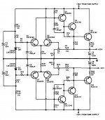
So I went back to have a look at two similar discrete regulators that I think might be simple and good options.
Kit Ryan's supply has the advantage of being completely bipolar, meanwhile Borbely's uses MOSFETs that you can't find now.
Your opinions over this are important to me.
One important thing mentioned on that article is that the author did consider the TL783, but considered the voltage drop too large: 10-15v. Indeed it is.
So I went back to have a look at two similar discrete regulators that I think might be simple and good options.
Kit Ryan's supply has the advantage of being completely bipolar, meanwhile Borbely's uses MOSFETs that you can't find now.
Your opinions over this are important to me.
Attachments
I agree: the TL783 would be problematic for your use, and with the total voltages exceeding the 125V limit, you cannot resort to any trick.The only problem I foresee for using a TL783 is how to wire it as negative regulator, except by using separate secondaries, and wiring the ground from the positive and the positive from the second regulator, using the ground of that regulator as negative.
Can I do that with three secondary wires? I think not.
The Kit Ryan example looks like a good choice, except it is vast overkill for 25mA: for such a low current, you don't need triples or even doubles: the ballast transistor can be simplified to Q3 & Q9.
I have probably other working examples in my files, I will try to find something suitable.
But you should follow Mark's advice, and ask the moderation to open a dedicated thread, since this has little to do with the denoiser
I agree: the TL783 would be problematic for your use, and with the total voltages exceeding the 125V limit, you cannot resort to any trick.
The Kit Ryan example looks like a good choice, except it is vast overkill for 25mA: for such a low current, you don't need triples or even doubles: the ballast transistor can be simplified to Q3 & Q9.
I have probably other working examples in my files, I will try to find something suitable.
But you should follow Mark's advice, and ask the moderation to open a dedicated thread, since this has little to do with the denoiser
I had already opened another dedicated thread, where I tried to get advice on how to use the 317/337 for high voltage.
There I also mentioned the Kit Ryan's regulator.
I just came here for the D-Noizator, which you do not recommend on my application.
I sent you a PM on the simulation you did for the Ryan's regulator.
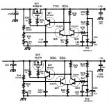
Be aware that R5 & R6 need to be the cream of the cream: generally, trimmers are noisy, unstable, non-linear but it does not matter when they are ~10% of the total resistance.
Here they are 100%.
When possible, connection in potentiometer mode improves matters, but with the 317, it is not possible
Back to fixed resistors it is then.
By my maths the R3/R4 of 240R gives 5.2mA. For +/- 15V with 5.2mA gives R5/R6 of 2.64k.
Req= product over the sum; using a 5k and a 5.62k resistor gives 2636.5ohm, which should be close enough.
Here is the new layout with the trimpot replaced with dual fixed resistors again.


Does anybody see any layout mistakes or is this likely to work as intended?
- Home
- Amplifiers
- Power Supplies
- D-Noizator: a magic active noise canceller to retrofit & upgrade any 317-based V.Reg.