You could also use a resistor in series with a pot, plus, add another resistor in // with that pot to get some ability to trim the voltage if it's necessary
You could also use a resistor in series with a pot, plus, add another resistor in // with that pot to get some ability to trim the voltage if it's necessary
I don't know how much current goes through that pot. The simulation is not good for seeing current on pots, at least on mine.
Another thing: apparently single turn ceramic pots are more reliable than multi-turn ones, so wouldn't a simulation allow having a ballpark on where the adjustable resistance value might be, then add a resistor in series with a 1-turn ceramic trimpot to be safe?
Fixed resistors are always preferable for critical applications.Back to fixed resistors it is then.
By my maths the R3/R4 of 240R gives 5.2mA. For +/- 15V with 5.2mA gives R5/R6 of 2.64k.
Req= product over the sum; using a 5k and a 5.62k resistor gives 2636.5ohm, which should be close enough.
Here is the new layout with the trimpot replaced with dual fixed resistors again.
View attachment 796455View attachment 796456
Does anybody see any layout mistakes or is this likely to work as intended?
The technique I use (and the industry uses) is to use a main resistor, slightly larger than the expected value, and in parallel a larger one, connected with machine turned receptacles.
This technique has the advantage that only the main resistor needs to be ultra-stable, and generally values in the E12 or E24 series give a sufficient granularity.
Once you have selected the definitive adjustment resistor, it can be soldered to the receptacles for a better durability
Last edited:
Here is a crude and simplified one (current limited to ~500mA, so probably a M type):Any LTSpice model for LM337?
Can't find any with Google.
Code:
*
*LM337 negative voltage regulator
*Connections   Input Adj. Output
.subckt LM337   8       1      19
.MODEL QN NPN (BF=50 TF=1N CJC=1P)
.MODEL QPOUT PNP (BF=50 TF=1N RE=.2 CJC=1P)
.MODEL QP PNP CJC=1P TF=2N
.MODEL DN D
.MODEL D2 D BV=12 IBV=100U
R10 25 6 1K
Q3 8 17 16 QPOUT
Q4 8 25 17 QP
R18 19 17 250
R19 19 16 .3
G1 8 6 1 18 .1
C7 6 2 .04U
R24 2 8 100
I_ADJ 0 1 65U
R26 8 25 200K
Q5 25 4 19 QP
R27 16 4 200
R28 7 4 7K
D1 8 7 D2
D2 8 6 DN
V1 18 19 1.25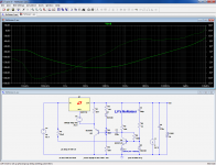
.ENDSTo start with, and as it was missing, I am uploading the original D-noisator proposal, only changing the original chip from 317 to LT1085, which is the model included in the LTSpice library.
Next I added the negative regulator, just changing the chip to LM337 and the transistor. All polarized parts were adjusted.
Regulation seems to happen alright, with different output values as it should be, but the resulting curves from positive and negative outputs are exactly the same, which of course shouldn't be so.
So something else has to be changed, and I ask to please tell me what. This should contribute to my further learning (and perhaps other's) on how to setup power supply simulations.
Attachments
You have completely messed up the original circuit.
Here it is again:
https://www.diyaudio.com/forums/att...r-retrofit-upgrade-317-based-reg-nonoiser-asc
The only thing you are allowed to change is R5 (and maybe R3 if you want to use a close but more convenient value).
You must not add resistors here and there, or modify the values of existing resistors.
For the negative part, just build the mirror image.
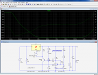
To test the output impedance, switch I1 on (AC1) and switch off the rest:
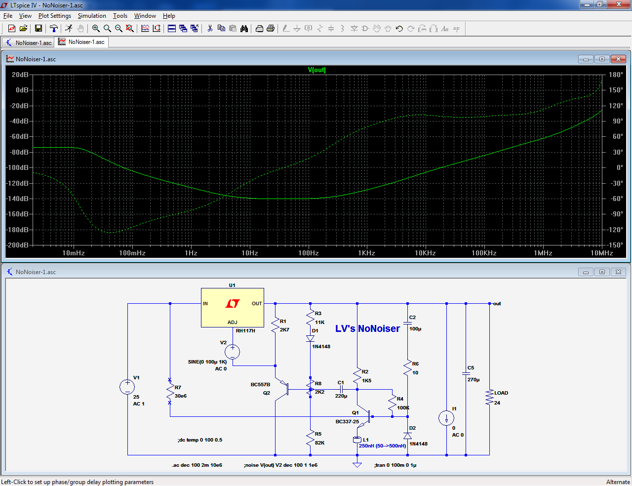
To test the PSRR, switch V1 on and switch off all the rest:
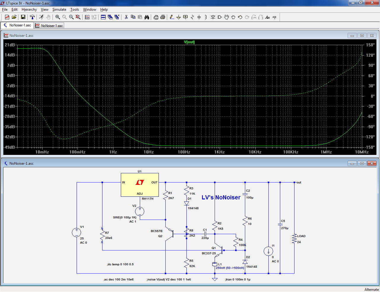
To test the attenuation of the noise from the 317, switch on V2 (its noise is not natively modeled in the model):
Here it is again:
https://www.diyaudio.com/forums/att...r-retrofit-upgrade-317-based-reg-nonoiser-asc
The only thing you are allowed to change is R5 (and maybe R3 if you want to use a close but more convenient value).
You must not add resistors here and there, or modify the values of existing resistors.
For the negative part, just build the mirror image.
To test the output impedance, switch I1 on (AC1) and switch off the rest:
To test the PSRR, switch V1 on and switch off all the rest:
To test the attenuation of the noise from the 317, switch on V2 (its noise is not natively modeled in the model):
Attachments
You have completely messed up the original circuit.
Here it is again
But I didn't upload the D_nonoiser. I uploaded the D_noizator, both in single and dual versions.
You are showing the D_nonoiser simulations. I didn't mess up anything.
On my simulations with the dual NoNoiser, I followed your instructions rigorously. But I didn't upload them yet.
The only thing I did on the NoNoiser simulations was change the R5 value (and its counterpart on the negative regulator), to get as close to 30v as possible at the output, and eliminated the R8 trimpot, also following your instructions.
Are we OK?
The only thing I did on the NoNoiser simulations was change the R5 value (and its counterpart on the negative regulator), to get as close to 30v as possible at the output, and eliminated the R8 trimpot, also following your instructions.
Are we OK?
It's a mixed bag: this file of yours is actually a denoizator:But I didn't upload the D_nonoiser. I uploaded the D_noizator, both in single and dual versions.
You are showing the D_nonoiser simulations. I didn't mess up anything.
https://www.diyaudio.com/forums/att...t-upgrade-317-based-reg-d_noisator_lt1085-asc
But that one (also yours) shows a dual nonoiser with issues:
https://www.diyaudio.com/forums/att...ofit-upgrade-317-based-reg-dnoisator_dual-asc
Not quite yet: we need to align on what is a modified/unmodified denoiser/nonoiser.On my simulations with the dual NoNoiser, I followed your instructions rigorously. But I didn't upload them yet.
The only thing I did on the NoNoiser simulations was change the R5 value (and its counterpart on the negative regulator), to get as close to 30v as possible at the output, and eliminated the R8 trimpot, also following your instructions.
Are we OK?
To make things easier, here are the positive versions of both, for a 30V output:
Edit: completely unrelated, but 40V input for a 317 makes me uncomfortable.
I would use a 317HV, to be completely safe with the input voltage
Attachments
Last edited:
I will do all the work that is necessary in order to learn what I want to learn. Can you help me?
How do I modify each setting to get that graph you show?
I asked for your asc file just because I had modified them trying to follow your directions, but I didn't get the right result.
And about the confusion with my uploaded files above, sorry I sent the wrong one.
Another question: why not simply delete the R8 trimpot, since the output is being set by R9 // R5?
Yes, at least on a one-off basis: a thread is not the ideal context for a comprehensive course, and if you need one, there are numerous (and free) resources available on the net.I will do all the work that is necessary in order to learn what I want to learn. Can you help me?
The LTspice thread here is also a good source for information:
Installing and using LTspice IV (now including LTXVII). From beginner to advanced.
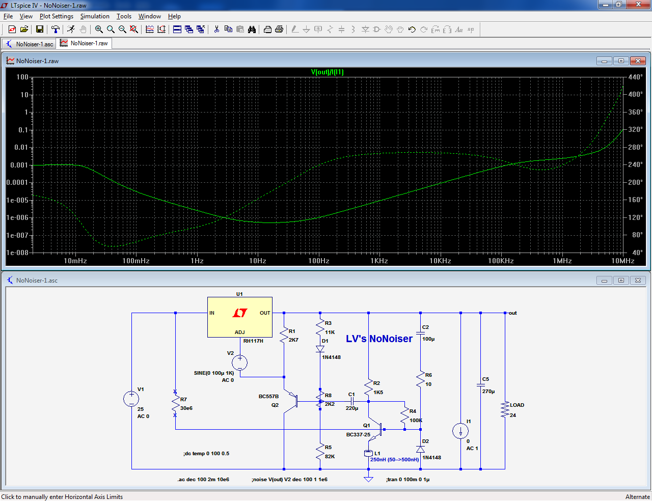
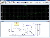
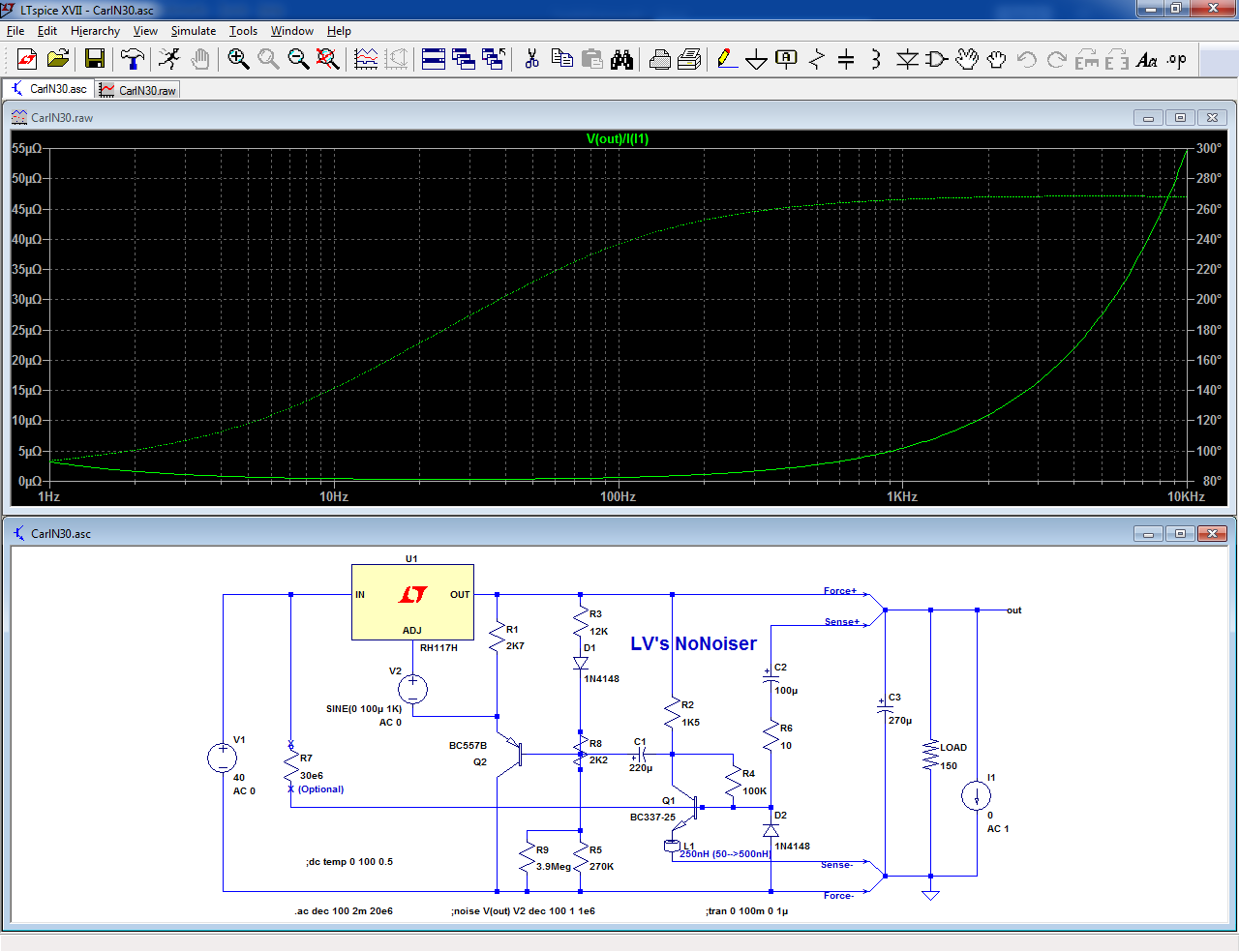
Assuming you have the AC sources set correctly (that's included in the asc), you need to right-click on a trace and edit it to something like V(out)/I(Iload) for the impedance.How do I modify each setting to get that graph you show?
You then right-click on the left axis to change it from dB to log or linear.
If you opt for linear, the correct units will be displayed:
In log, the values will be numerically correct, provided you have chosen AC1
Yes, it can be deleted without problemAnother question: why not simply delete the R8 trimpot, since the output is being set by R9 // R5?
Note that noise simulations are still of another kind, and just adding a .noise directive will not always give meaningful results, because some of the ADI models do not include noise (that's the case for the RH117=LM317), which is why I used an external source to assess the noise, but one thing at a time: first master basic things (PSRR needs no configuration, it works just by clicking on the output node), when you feel confident with basic things, you can up to the next level
Attachments
Here's something odd . While I was testing the DeNoiser for the right base R to get the desired Vce, output voltage dropped with loads bigger than around 80 mA , and began the up and down wave to the exact output voltage again. Weird . Cutting the collector R , so disabling the DeNoiser , no problems, so it wasn't the LM317. Tried a few things , even revert to all the original values , still problem . Turns out it needed a cap in front of the LM . The wires from 2 different power sources (combined to get around 20 V) , were very long , and while this didn't create a problem for the LM alone , with the DeNoiser it was a problem.
btw : while you (Elvee) , already pointed out that the Vce doesn't matter as long as it is in the lineair region of the transistor , I wanted it to be like your original . Turns out for a collector R of 3k6 (in stead of your 1k8) , 390k gave 4,5V like yours.
btw : while you (Elvee) , already pointed out that the Vce doesn't matter as long as it is in the lineair region of the transistor , I wanted it to be like your original . Turns out for a collector R of 3k6 (in stead of your 1k8) , 390k gave 4,5V like yours.
Yes, at least on a one-off basis: a thread is not the ideal context for a comprehensive course, and if you need one, there are numerous (and free) resources available on the net.
The LTspice thread here is also a good source for information:
Installing and using LTspice IV (now including LTXVII). From beginner to advanced.
Assuming you have the AC sources set correctly (that's included in the asc), you need to right-click on a trace and edit it to something like V(out)/I(Iload) for the impedance.
You then right-click on the left axis to change it from dB to log or linear.
If you opt for linear, the correct units will be displayed:
In log, the values will be numerically correct, provided you have chosen AC1
Perhaps you may have noticed that I uploaded a Jung superregulator simulation at the other thread I opened, about RIAA power supplies.
It might take me a long time to learn how to use LTSpice to get to master it as you do.
Perhaps if I upload the simulations asc files you can set the right parameters and show the graph results? Particularly impedance and noise.
Would that be possible or would be of any interest to do, to carry on a comparison. AFAIK it has never been done yet.
Note that noise simulations are still of another kind, and just adding a .noise directive will not always give meaningful results, because some of the ADI models do not include noise (that's the case for the RH117=LM317), which is why I used an external source to assess the noise, but one thing at a time: first master basic things (PSRR needs no configuration, it works just by clicking on the output node), when you feel confident with basic things, you can up to the next level
As I said, that might take a very long time, and getting results like the ones I am after might be interesting information for many others on DIYaudio.
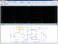
OK, I changed V(out) to V(out)/I(I1) and magnitude on the left to Linear.
Why am I not getting the same curve you showed?
To what values do I adjust the ohms on the left?
Why am I not getting the same curve you showed?
To what values do I adjust the ohms on the left?
Attachments
Last edited:
Please take a look at the "Looking for supply for RIAA" thread.
I just uploaded the curve I'm getting for the Jung regulator simulation I uploaded there.
Are the results OK?
I just uploaded the curve I'm getting for the Jung regulator simulation I uploaded there.
Are the results OK?
Has anyone actually tried the DeNoiser with LM337 ? Not the software sim !
I have and it is disappointing. While the LM317 does it's job with the D-N , well, after a input cap , the same bad behaviour was NOT solved with the LM337.
I bought 2 ON LM337's from a fairly trusted source and they do their job well
without the D-N . Their coolplate is thinner 0,5 mm while normal TO220 are 1
mm. Their Vref differs only 2 mV . I also bought the desired ST LM337's but they
looked old ... and they didn't work, not even stand-alone , maybe their pins are
different but data sheet says the same. So probably fakes or ESD-ed. Luckily
they're cheap.
I trusted the "in principle the DeNoiser will work with LM337 and other
regulators", so I didn't test them and made a PCB . I was wrong. With the
DeNoiser , having more than a couple of 10's mA load , the output dropped , and dropped
more with higher loads . Going back to no load , the output snaked again around
the right output voltage like switching on. Both LM337's did exactly the same. No
amount of capacity at the input and/or output helped and yes I checked polarity of
the caps of the D-N , PNP transistor . I didn't check twice , I did it multiple times
and of course during the PCB design stage. Freq counter didn't detect oscillation .
When I short the CE of the transistor , all is normal , working like there is no
DeNoiser , shorting the diode over BE did the same.
That's where I'm at. No critism on Elvee , the title says DeNoiser for LM317, but if you use it for audio upgrades , where there are - and + supplies , you might make things a lot worse if
the D-N isn't playing well with the existing LM337.
Now I'm thinking of only using the D-N with the LM317 and use the LM337 with
just the Ref cap . Seriously disappointed , opamps's PSRR is always worst to the
neg supply. Using a LM317 for both sides is not posible because they have a shared
ground and PCB is already made and too compact to change and I don't like the
ground interupted by a regulator. My ground (0) goes straight from the transformer
with thick copper to the CRC and regulators to the amp PCB.
So be warned and test your circuit before making a PCB and solder everything on
it.
- Home
- Amplifiers
- Power Supplies
- D-Noizator: a magic active noise canceller to retrofit & upgrade any 317-based VReg