I´m all green of jealousy now, i wish i could make that nice stuff.
All my stuff look like s h i t and work like s h i t 🙁
All my stuff look like s h i t and work like s h i t 🙁
Hi
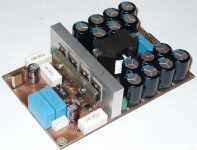
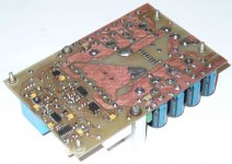
Damn that is something else... nice job, hope to see some scope pic soon. This is IR2110 version? what else do you got on it?
Damn that is something else... nice job, hope to see some scope pic soon. This is IR2110 version? what else do you got on it?
FPGA-based all-digital amplifier with post-filter feedback
Hi!
I would invite You for the Scientific Student Conference in my school, BUTE, will be held at Friday, 16th October.
We built an FPGA-based all-digital Class-D post-filter fed back digital amplifier. At the conference, we review the theory of the operation, and present the operation of the working amplifier under different conditions. Eventually, you will get a recollection CD-ROM containing the papers of the performances over the sections.
The conference's official website: http://avalon.aut.bme.hu/~lengyel/tdk/TDKProgram2007.htm
Our paper:
http://centaur.sch.bme.hu/~dgyuri/D...u_erosito_direkt_digitalis_szabalyozassal.pdf
Best regards,
Nagy Gyula
Hi Gyula!
It will be in Noverber not October 🙂
Could you tell me when you start the conference?
It will be in Noverber not October 🙂
Could you tell me when you start the conference?
Hi, Bender!
maybe the schematic of your 2nd amplifier (I saw a 2110 on board) will help me understanding about how can I make this without deteriorate the THD 🙂
Thanx
maybe the schematic of your 2nd amplifier (I saw a 2110 on board) will help me understanding about how can I make this without deteriorate the THD 🙂
Thanx
Hi, zlazar! I didn't draw schematic yet, keep it in my mind. 😉. I'll draw and post it later, with results of THD measurements etc. imho it's impossible avoid thd deteriorattion using 2110 instead 20124 ( carrier based amp).
dear Bender.ru
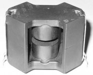
I'm looking for RM cores (used for your D_trinagle : RM 10, material N87). Unfortunatelly the gapped core exist only with N48 and N41 material. Do U put something to keep the 1.3mm distance for the airgap, or I missundersted something with?
RM 10 cores link: http://www.epcos.com/inf/80/db/fer_07/rm_10.pdf
Bender in this other prototype,what ic and feedback did you use?
Is it pre feedback?
Have you already tried Fredos front end in bridge using differential amp op in feedback path?If so ,did you use post feedback?
Is it pre feedback?
Have you already tried Fredos front end in bridge using differential amp op in feedback path?If so ,did you use post feedback?
Did anyone tried Post filter feedback in bridge mode.......
I am planning to do it by taking the feedback from both outputs and then convert it inot single ended through a differential opamp and then feed it directly to comparator input just like UCD style......
Any suggestions??
I am planning to do it by taking the feedback from both outputs and then convert it inot single ended through a differential opamp and then feed it directly to comparator input just like UCD style......
Any suggestions??
I may probably have to face a self oscillating full bridge soon, and common mode errors are evil in differential amplifiers, particularly at high frequencies, so I may probably just ground the control circuit to one end...
Evita,Eva said:so I may probably just ground the control circuit to one end...
1.You are talking about turning the negative side rail for low side mosfet into ground reference and i.e. single supply operation....
OR
2. Turning one of the output nodes of H-Bridge into ground reference and make the supply floating.......
Meanwhile i am intrested in 3-Level PWM, but it has got problems with using single differential inductor......or i have to use seperate inductors for each node ....
Eva said:Kind of option 2 😉
Then wouldn't it will become a EMI inferno generator, just because of the switching floating rails.......
I have seen a car amp schematic with this topology in BD mode....The floating rails were emitting tons of EMI
- Status
- Not open for further replies.
- Home
- Amplifiers
- Class D
- D AMP is back !!!